[Bertho] really enjoyed pawing through the pile of projects submitted to the 7400 logic contest. But one thing kept hitting him with the vast majority of the entries: decoupling capacitors were missing from the circuits. If you’ve worked with microcontrollers or digital logic chips you probably know that you’re supposed to add a small capacitor in between the voltage and ground pins for decoupling purposes. But do you know why? [Bertho] put together a great post that looks that the benefits of using decoupling capacitors in your circuits.
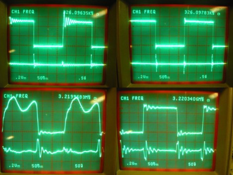
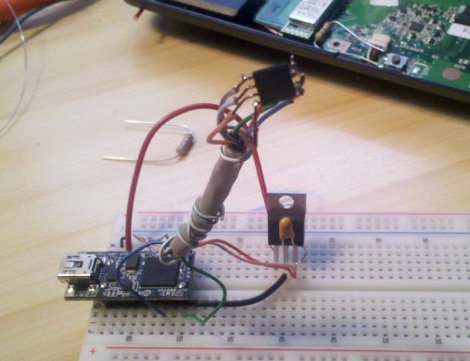
He set up a circuit using a 74HC04 inverter and put it to the test. The image above shows current measurments with the inverter under load. Images on the right show a decoupled circuit and the ones on the left shows a circuit without that capacitor. You can see that the decoupled circuit has much smoother signals when driven high. But it’s not just the smoothness that counts here. [Bertho] goes on to discuss the problem of slow rise-time caused by a dip in current flowing into a chip’s VCC pin. It can take a long time to get above the threshold where a chip would recognize a digital 1. Throwing a capacitor in there adds a little reservoir of current, just waiting to fill in when the power rail dips. This feeds the chip in times of need, keeping those logic transitions nice and snappy.


