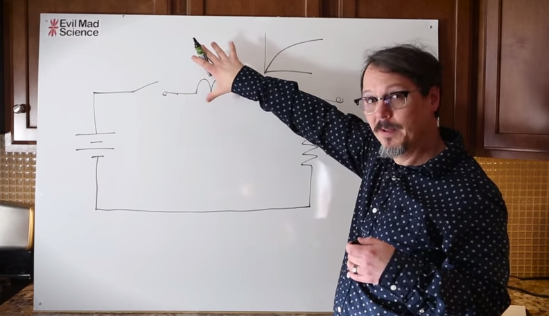
We all know that the reason the electrical system uses alternating current is because it’s easy to step the voltage up and down using a transformer, a feature which just isn’t possible with a DC system… or is it? Perhaps you’ve heard of mysterious DC-DC transformers before but never really wanted to look at the wizardry that makes them possible. Now, SparkFun Director of Engineering [Pete Dokter] has a tutorial which explains how these mysterious devices work.
Known as buck converters if they step the input voltage down and boost converters if they step the voltage up, [Pete] explains how these circuits exploit the properties of an inductor to resist changes in current flow. He goes into exquisite detail to explain how components like transistors or MOSFETs are used to switch the current flow to the inductor very rapidly, and just exactly what happens to the magnetic field which makes these devices possible.
The video gives a good amount of background knowledge if you’ve always wanted to understand these devices a little bit better. There are also a few projects floating around that exploit these devices, such as one that uses an AVR microcontroller to perform the switching for a small circuit, or another that uses the interesting properties of these circuits to follow the I-V curve of a solar panel to help charge a bank of batteries. The possibilities are endless!


That was actually pretty good.
Very informative. I’ve been using buck and boost regulators for a while, but no real idea of how it worked.
This one was really enlightening too:
https://www.youtube.com/watch?v=l4i76jKmI8g
So, can somebody have Miko explain this?
As far as I know, the reason we use AC in our electrical system is because it is much more efficient to transmit power at high voltage, high frequency than at DC.
Transformers are technology that help make it safe and practical to do so. Especially with the technology available at the time they were developing the grid.
In more detail:
Higher voltage is better for transmission because you lose less power due to the resistance of the power line. (V=IR, so the voltage drop/loss across the power line is proportional to the current, and P=IV, so if you increase the voltage you can transmit the same power at a lower current, reducing ohmic losses.)
AC makes this reasonable/economic to do because you just need a transformer (no active components) to step up/down the voltage on each end.
When it comes to AC and long transmission lines I believe losses due to reactance are as much a factor than losses due to the resistance of the cables is. A reason why we see HVDC for some of the longer transmission lines I assume.
I am not sure if this is true since AC results in the skin effect and proximity effect both of which, according to my knowledge, increases the resistance. These two effects become worse as the frequency increases. Now, high freq AC could does mean we need smaller transformers, but that does not offset the increases in cable size necessary.
Here is a relevant post and discussion on the matter: http://www.reddit.com/r/AskElectronics/comments/197l8q/if_the_entire_power_grid_could_be_redesigned_from/
AC is going to be use for a good portion of the electrical grid for the foreseeable future, the reason is not because AC is more efficient than DC, it isn’t. For longer transmission lines High Voltage Direct Current is more efficient than AC. When it come to neighborhood,local, intermediate, and regional grids DC isn’t going to be used for all the reasons why DC lost the current war. For that reason I don’t understand the Reddit discussion For the foreseeable future hardware needed to build a DC grid is likely to be more expensive and less robust that current AC grid hardware with very little payout.
Explaining the concept is good, however,
leaving out the equations is bad.
The missing equations identify the size of the parts you use based on input voltage, output voltage, output current, etc.
The missing equations explain the benefits over a linear regulator with a direct comparison.
Nice,
More details
http://simonthenerd.com/files/smps/SMPSBuckDesign_031809.pdf
one step ( more ) Mppt ( how to catch “all” the electrons )
https://www.youtube.com/watch?v=0ItjKs7aJFM
That was well-done!
For a small amount of extra design effort, and the addition of another inductor and capacitor, you can make a SEPIC converter topology, which will buck or boost into a load. That’s useful if your source is going to vary across what your load needs, like a 12v supply in a car, where VIN goes from 14V whilst running, down to 8V when the car is starting up. Most boost chips will work okay in a SEPIC topology as well. Wikipedia has a reasonably good overview of it, as well as the alternative Cuk topology that does something similar.
I hate to be critical of someone taking their time to explain things for others, but I didn’t like this video. It felt like he set up a camera and started talking, rather than really preparing and thinking what he wanted to say.
Here is a Dave Jones (eevblog) explanation of linear vs buck regulators, aimed at the same level of understanding as the Sparkfun video (quick overview, no math or rigor): https://www.youtube.com/watch?v=cM7t1Mpu7s4
I don’t see that as an issue. It’s not a paid college course. It’s a guy sharing what he knows as he finished up a project. And yes, I understand that it almost a commercial for buying buck converters from EMS, but it also showed why I should drop the old linear regulators and go with bucks. Although I would like a follow up on dimming with buck/boost.
If anything I would fault Dave for using a marker board instead of drawing the graphics out digitally and overlaying them or using them in the background. Something a little more professional looking seeing how he is doing videos as a living. Since he is “preparing and thinking [about] what he wanted to say”, he could make the graphics as he is preparing.