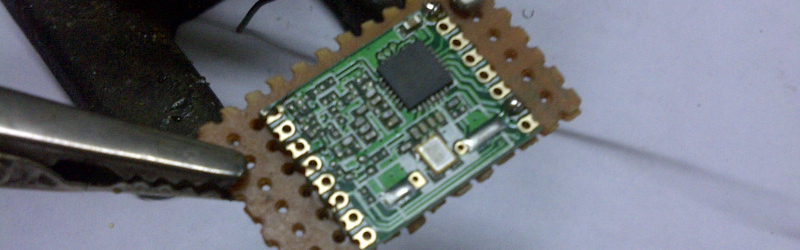
Radio, WiFi and similar modules are getting smaller by the day. Trouble is, they end up having non-DIY-friendly, odd pitch, mounting pads. Sometimes, though, simple hacks come around to help save the day.
[Hemal] over at Black Electronics came up with a hack to convert odd-pitch modules to standard 2.54mm / 0.1″. The process looks simple once you see the detailed pictures on his blog. He’s using the technique to add 2mm pitch modules like the ESP8266 and XBee by soldering them to standard perf board. Once they are hooked to the board, just add a row of male header pins, trim the perf board and you’re done. Couldn’t get simpler.
Another technique that we’ve seen is to solder straight across the legs and cut the wire afterward. That technique is also for protoyping board, but custom-sized breakout boards are one good reason to still keep those etchants hanging around. If you have other techniques or hacks for doing this, let us know in the comments.


Are you drunk? This has bin around a long time, like with dead-bug chips! Or am I missing something really special about this?
Yeah i have been using this method for years, lets see someone do this with an 800 pin FPGA than call that brilliant
Like this XP http://dangerousprototypes.com/forum/viewtopic.php?f=2&t=4683
Holy crap!
damn!
That is amazing. Bet he has a good workstation and a nice stereo microscope. If he did that on a coffee table using a club iron while watching tv, then he is the master of all.
Just… WOW.
I was pretty proud of my dead-bug 100-pin TQFP, but this puts that to shame, I won’t even bother linking it.
Nah… I’m still pretty proud… This thing worked for over six months hanging out the back of my laptop. Probably still works, actually.
https://sites.google.com/site/geekattempts/_/rsrc/1387728019474/home-1/lvds-single-to-dual-converter/lvds-single-to-dual-converter-1/cropped.jpg (can remove the ‘cropped.jpg’ to see the main page)
slow news day, I guess.
yeah, when this qualifies as HAD content, it MUST be a really slow news day.
what’s next? use of .1uF caps as bypasses, but soldered right across pins 7 and 14? I haven’t seen that for a while. maybe its ‘new’ to some HAD readers? ;)
Can we call that a cap breakout? XP
I usually just bend the ^%#$ out of some regular header pins, albeit that typically only works in groups of 3-5, This is better, I think.
Or get extra-long headers… you can do a lot of this sorta stuff with those. Of course, they add the 3rd dimension, that this removes.
uhhhhhh. what’s the hack here? “use wire to attach something to perfboard”? Am I missing something
Wow. I see the trolls are out in full force.
I think that people should bear in mind that no everyone is an experienced engineer/superhacker. Some folks can actually make use of helpful tips like this.
+1. I mean, c’mon. Some of us are Engineers, not Physicists. :-)
Are you proposing a series of articles on “hacking for beginners”? Like the Fail Of The Week theme?
That would quell the grumbles of “this isn’t new” while still providing education / inspiration for newer hackers.
+1 Good idea. I would read it religiously.
Trolls? How is letting people know your opinion the same as trolling?
You should read up on what trolling really is.
http://preview.tinyurl.com/33z8vdu
I already designed a single-sided self-etchable ESP8266 breadboard-adapter board with voltage regulator and flash button.
See http://lookmanowire.blogspot.com
After cutting the perfboard, at least have the decency to file the edges before you take a picture. Brrrr….
or maybe just buy it already done and save the clever workmanship for something else
http://www.ebay.com/itm/1PCS-ESP8266-Esp-07-Remote-Serial-Port-WIFI-Module-IO-adapter-plate-Expansion-/181646783057?pt=LH_DefaultDomain_0&hash=item2a4afdf251
Sure, but then again you could say that about almost every HaD post. You could say it about almost everything DIY! Way to go.. you just obsoleted our whole hobby. I hope you are happy with yourself! Now what do we do? Slouch all day in our store-bought couches eating store-bought junk food watching cable TV?
so let me get this straight
if you didn’t smelt your own silicon from beach sand then you are cheating
if you didn’t key in the bootloader from the front panel switches then you are cheating
you know, the point of hacking is to ACCOMPLISH SOMETHING, not brag about how much time you wasted
They are much cheaper on AliExpress: http://www.aliexpress.com/w/wholesale-esp8266-adapter.html?site=glo&groupsort=1&SearchText=esp8266+adapter&SortType=price_asc&isUnitPrice=y&shipCountry=us&isFreeShip=y
The thing that I don’t like about this method is that you are starting with your wires at the wider spacing (the perfboard) down to the narrower spacing. If you later decide you need access to a pin that is between two others that you already ran wires to it’s going to be tough to run that without causing a short.
I prefer the wrapping method.
Place some sort of objects on the top plus bottom of the module to serve as spacers. Then wrap a piece of uninsulated wire around the module with the wire traveling through the dips in each pad. Then add solder to each pad. Now cut the wires, top on oneside, bottom on the other side so that each pad now has a separate piece of wire soldered to it. Count pins and solder the correct size headers onto your perfboard. Either glue or use double sticky tape to stick the module to the perfboard and then solder your wires to the headers.
This way you are fanning your wires out as you go to the headers rather than bringing them together as you go to the module. It gives you every pin without as much worry about shorts.
No, I don’t think there is anything original about this method. I just didn’t see it on the list yet.
+1 to that method (Me), works for pretty much anything with pads on the sides of the chip/board too. Use modeling clay or blue tak(tm) to hold the coil of wire in place while you wrap it prior to soldering, test your clay first to ensure it doesn’t melt or burn. Adjusting the spacing is easy if things start to unravel. If you need pictures… or can’t figure out what I am talking about, you have no imagination. ( }:~) I had to do a little trolling, wouldn’t be HAD if I didn’t)
Look at the photos in the thread below, but ignore the text (I fleshed things out at a painfully basic level, because I was teaching some people basic electronics at the time)
http://www.exisle.net/mb/index.php?/topic/65765-cheapeasy-homemade-smd-to-dip-adapters/
Wow. Brilliant!
Not the best of cameras on those blackberry 9800’s then eh.
The problem isn’t with the content, it’s with the title and summary. A better title would be “Electronics Basics: Convert castellated pads to DIP”.