The SoM on an evaluation board, with two LEDs shining, one USB-C cable connected for power and another plugged into the OTG port

New Part Day: X1501 Makes For A Tiny And Open Linux SoM

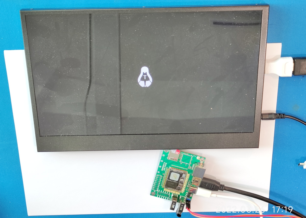
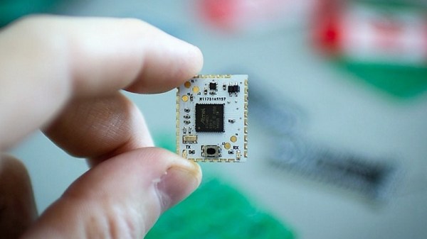
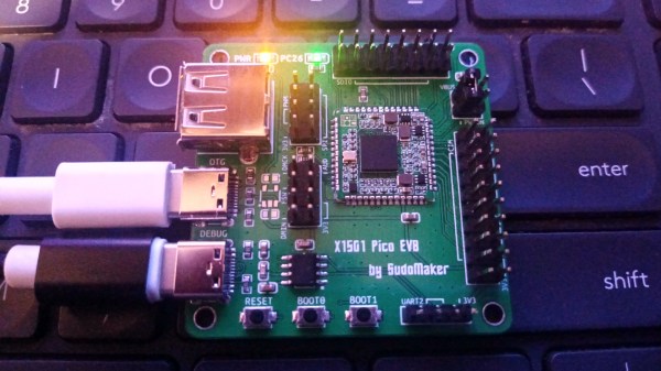
Ever wanted to run Linux in an exceptionally small footprint? Then [Reimu NotMoe] from [SudoMaker] has something for you! She’s found an unbelievably small Linux-able chip in BGA, and designed a self-contained tiny SoM (System on Module) breakout with power management and castellated pads. This breakout contains everything you need to have Linux in a 16x16x2mm footprint. For the reference, a 16mm square is the size of the CPU on a Raspberry Pi.

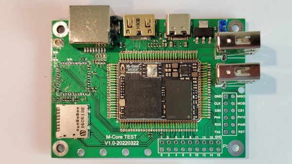
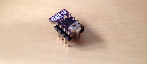
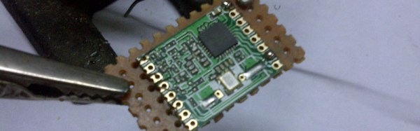
This board isn’t just tiny, it’s also well-thought-out, helping you put the BGA-packaged Ingenic X1501 anywhere with minimal effort. With castellated pads, it’s easy to hand-solder this SoM for development and reflow for production. An onboard switching regulator works from 6V down to as low as 3V, making this a viable battery-powered Linux option. It can even give you up to 3.3V/1A for all your external devices.

The coolest part yet – the X1501 is surprisingly friendly and NDA-free. The datasheets are up for grabs, there are no “CONFIDENTIAL” watermarks – you get a proper 730-page PDF. Thanks to this openness, the X1501 can run mainline Linux with minimal changes, with most of the peripherals already supported. Plus, there’s Efuse-based Secure Boot if your software needs to be protected from cloning.

More after the break…

Continue reading “New Part Day: X1501 Makes For A Tiny And Open Linux SoM”

An M-Core module plugged into its devboard. Around it are Ethernet, HDMI, Type-C, two USB-A ports, one MicroSD card socket and one unpopulated footprint for a WiFi module

MangoPi To Bring A SD-Card-Sized Linux Module

Today’s Diminutive Device is a small castellated System-On-Module (Twitter link, nitter proxy) from [MangoPi] called M-Core, with a quad-core A53 CPU and 1 GB of RAM. As such, it’s very capable of running Linux, and even sports an HDMI output! Taking a closer look at the devboard picture, we can spot traces for three USB 2.0 ports, what seems to be two SDIO interfaces for MicroSD or WiFi cards, and an Ethernet MagJack with its termination network. This is a decent set of interfaces, rivaling what we’d expect out of a Pi Zero!

More importantly, this module is as small as an SD card itself – or as an OLED display that we hobbyists sprinkle onto our projects. Having power of Linux in such a small footprint is certainly something to behold! The back of the module is mostly flat, save for a few decoupling capacitors on the other side of the CPU – it seems, an Allwinner H616. On top of it, we can see the CPU itself, a small buck regulator and a DDR3 RAM chip, as well as tightly-packed passives. There’s even an unpopulated footprint for a DFN8 QSPI flash chip – with a lightweight enough OS build, you could perhaps dedicate your MicroSD card to storage only.

The devboard for uses the “FlexyPins”-like connectivity technique we’ve covered recently, and [MangoPi] say they bought those pins on TaoBao. We can’t help but be a bit amused at the thought of putting HDMI through such connections, but it seems to work well enough! Castellated modules like these are relatively easy to work with, so it shouldn’t be hard to literally pop this module out of the devboard and figuratively pop it onto your PCB. Next step is, reportedly, porting Armbian to this board, likely solving quite a few software support hurdles.

MangoPi have been posting updates on their Twitter page over the last few weeks, and, as it comes with the format, a lot of questions are left unanswered. Why does the devboard only show a single linear regulator of the kind we typically expect to deliver 1 A at most? Will we get higher-RAM versions? What’s the price going to look like? Will this module ever get to market? We can only hope, but if it does indeed, we are sure to see a few projects with these, whether it’s smart glasses, smart displays, phones, handhelds or malicious wall chargers. As usual, community makes or breaks an SBC, and we shall watch this one closely.

We thank [WifiCable] and [DjBiohazard] for sharing this with us!

DIY castellated PCB connectors

Snip Your Way To DIY PCB Castellations

Castellated PCB edges are kind of magical. The plated semicircular features are a way to make a solid, low-profile connection from one board to another, and the way solder flows into them is deeply satisfying. But adding them to a PCB design isn’t always cheap. No worries there — you can make your own castellations with this quick and easy hack.

Scissors cutting a PCB through vias to make castellations[@CoilProtogen] doesn’t include much information in the Twitter thread about design details, but the pictures make it clear what the idea is here. OEM castellations are really just plated areas at the edge of a board that can be used to tack the board down to another one without any added hardware. The hack here is realizing that lining up a bunch of large-diameter vias and cleaving them in half with a sharp pair of scissors will result in the same profile without the added cost. The comments on the thread range from extolling the brilliance of this idea to cringing over the potential damage to the board, but [@CoilProtogen] insists that the 0.6-mm substrate cuts like butter. We’d worry that the plating on the vias would perhaps tear, but that seems not to be the case here.

The benefits of a zero-profile connection are pretty clear in this case, where castellated PCBs were used to replace bulky header-pin connectors on a larger PCB. We can see this technique being generally useful; we’ve seen them used to good effect before, and this is a technique we’ll keep in mind for later.

DIY CircuitPython Brain Snakes Into Small Spaces

Whether you’re new to electronics and programming, or you were bit-banging bare metal long before hair metal, CircuitPython is a great tool for getting a project up and working without all the fuss. The boards show up as mass storage devices, and programming consists of editing the Python file and saving it back to the board.

The only hard part about CircuitPython is trying to cram those official boards into small projects. [Kevin Neubauer] got tired of making his own board every time and came up with a slim system-on-module that has all the core functionality of CircuitPython. CircuitBrains Deluxe has regular holes for using headers, but also has castellated pads so he can solder these modules directly to a larger project PCB. [Kevin] says these are still in the testing and cost-optimization phase, but we would totally buy a few of them.

[Kevin] probably has a programming method for this module in mind already. But if you find yourself mystified by castellated pads, take a look at this pogo pin programmer built for ESP8266s. If your problem is pitch-related, maybe you can save the day with a breakout board.

Thanks to [Drew Fustini] for the tip!

Save Some Steps With This Arduino Rapid Design Board

We’re all familiar with the wide variety of Arduino development boards available these days, and we see project after project wired up on a Nano or an Uno. Not that there’s anything wrong with that, of course, but there comes a point where some hobbyists want to move beyond plugging wires into header sockets and build the microcontroller right into their project. That’s when one generally learns that development boards do a lot more than break the microcontroller lines out to headers, and that rolling your own design means including all that supporting circuitry.

To make that transition easier, [Sean Hodgins] has come up with a simple Arduino-compatible module that can be soldered right to a PCB. Dubbed the “HCC Mod” for the plated half-circle castellations that allows for easy soldering, the module is based on the Atmel SAMD21 microcontroller. With 16 GPIO lines, six ADCs, an onboard 3.3 V regulator, and a reset button, the module has everything needed to get started — just design a PCB with the right pad layout, solder it on, and surround it with your circuitry. Programming is done in the familiar Arduino IDE so you can get up and running quickly. [Sean] has a Kickstarter going for the modules, but he’s also releasing it as open source so you’re free to solder up your own like he does in the video below.

It’s certainly not the first dev module that can be directly soldered to a PCB, but we like the design and can see how it would simplify designs. [Sean] as shown us a lot of builds before, like this army of neural net robots, so he’ll no doubt put these modules to good use.

Continue reading “Save Some Steps With This Arduino Rapid Design Board”

What’s Tiny, Has Eight Legs, And Acts Like An Arduino?

Back in the late 1970s, comedian Steve Martin had a bit about “Let’s get small!” Over on Hackaday.io, [Daniel Grießhaber], has taken that call to heart. He’s been working on DIL-Duino, a minuscule form factor Arduino in an 8-pin DIP format.

Built with an ATtiny85, the board has an area of just under 75 square millimeters (less than 8 mm x 10 mm). If you add the USB port, it still comes in at just over 144 square millimeters. [Daniel] found other small Arduino boards like the Olimexino-85s and the Nanite are not as small as his design.

The module has a QFN CPU and castellated holes around the perimeter for mounting. With pin headers, this would easily fit into a breadboard (as [Daniel] shows) or you could mount it directly to another board like a surface mount device. In fact, that’s the reason for using castellated holes: you can inspect that the solder joint at the mating SMD pad is good. You sometimes hear the technique called half-vias or leadless chip carrier.

If you note, [Daniel] used an oversized board with full holes around the perimeter and then had the board maker score the board, so the holes are cut in half. This is a better technique than trying to drill half holes on the board edge, which is difficult to do.

Naturally, this isn’t the first tiny Arduino we’ve seen. If you are an ARM fan, there’s some little bitty cards for it, too, although not quite as small as DIL-Duino.

Castellated Breakout Is Pitchin’ Brilliant!

Radio, WiFi and similar modules are getting smaller by the day. Trouble is, they end up having non-DIY-friendly, odd pitch, mounting pads. Sometimes, though, simple hacks come around to help save the day.

[Hemal] over at Black Electronics came up with a hack to convert odd-pitch modules to standard 2.54mm / 0.1″. The process looks simple once you see the detailed pictures on his blog. He’s using the technique to add 2mm pitch modules like the ESP8266 and XBee by soldering them to standard perf board. Once they are hooked to the board, just add a row of male header pins, trim the perf board and you’re done. Couldn’t get simpler.

Another technique that we’ve seen is to solder straight across the legs and cut the wire afterward. That technique is also for protoyping board, but custom-sized breakout boards are one good reason to still keep those etchants hanging around. If you have other techniques or hacks for doing this, let us know in the comments.