Diodes: The Switch You Never Knew You Had

Vishay's take on the 1N4148 data sheet (PDF), describing it as a switching diode.
Vishay’s take on the 1N4148 data sheet (PDF), describing it as a switching diode.

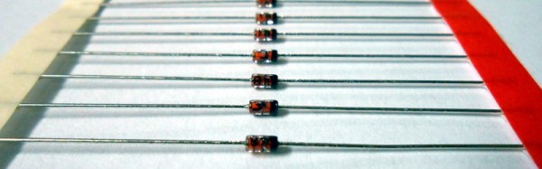
When looking across the discrete components in your electronic armory, it is easy to overlook the humble diode. After all, one can be forgiven for the conclusion that the everyday version of this component doesn’t do much. They have none of the special skills you’d find in tunnel, Gunn, varicap, Zener, and avalanche diodes, or even LEDs, instead they are simply a one-way valve for electrical current. Connect them one way round and current flows, the other and it doesn’t. They rectify AC to DC, power supplies are full of them. Perhaps you’ve also used them to generate a stable voltage drop because they have a pretty constant voltage across them when current is flowing, but that’s it. Diodes: the shortest Hackaday article ever.

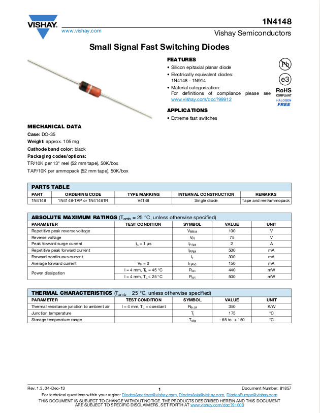
Not so fast with dismissing the diode though. There is another trick they have hiding up their sleeves, they can also act as a switch. It shouldn’t come as too much of a shock, after all a quick look at many datasheets for general purpose diodes should reveal their description as switching diodes.

So how does a diode switch work? The key lies in that one-way valve we mentioned earlier. When the diode is forward biased and conducting electricity it will pass through any variations in the voltage being put into them, but when it is reverse biased and not conducting any electricity it will not. Thus a signal can be switched on by passing it through a diode in forward bias, and then turned off by putting the diode into reverse bias.

Continue reading “Diodes: The Switch You Never Knew You Had”

Laser Cutting A Wooden Dymaxion Globe

Everyone knows that globes are cool — what else would you use as the centerpiece of your library/study? But, sadly, making your own isn’t a simple process. Even if you had a large (preferably hollow) sphere to work with, you’d still have to devise a clever way of printing the map in sections that can be glued to the curved surface. Wouldn’t it be easier if you could just laser cut flat sections, and assemble them to form a faceted “globe?”

Well, it is, and you can! Because, [Gavin] over at tinkerings.org (a Hackaday favorite) has created the files to do just that! This map projection, originally designed by the very interesting Buckminster Fuller, is designed to be either laid flat or three-dimensionally on an icosahedron (a 20-sided polyhedron). That makes it perfect for laser cutting, as each of the 20 faces can be cut from flat stock.

600px-fuller_projection_with_tissot27s_indicatrix_of_deformation

Continue reading “Laser Cutting A Wooden Dymaxion Globe”

Christmas Lights Done The Hard Way

It’s that time of the year again when you gotta start worrying if you’ve been naughty enough to not receive any gifts. Hopefully, Blinky Lights will appease St. Nick. Grab a strip of RGB LEDs, hook them up to an Arduino and a Power supply, slap on some code, and Bob’s your Uncle. But if you want to retain your hacker cred, you best do it the hard way. Which is what [roddersblog] did while building his Christmas Starburst LED Stars this year — and bonus points for being early to the party.

christmas-lights-the-hard-way
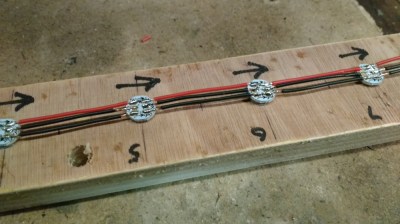
For starters, he got panels (as in PCB panels) of WS2812 boards from eBay. The advantage is it lets you choose your own pitch and strand length. The flip side is, you need to de-panel each board, mount it in a jig, and then solder three lengths of hook up wire to each LED. He planned for an eight sided star with ten LED’s each. And he built three of them. So the wiring was, substantial, to say the least. And he had to deal with silicone sealant that refused to cure and harden. But nothing that some grit and determination couldn’t fix.

For control, he choose the PIC16F1509 microcontroller. This family has a feature that PIC calls the “Configurable Logic Cell” and this Application Note describes how to use CLC to interface the PIC to a WS2811. He noticed processing delays due to C code overheads that caused him some grief. After some experimentation, he re-wrote the entire program in assembly which produced satisfactory results. You can check out his code on the GitHub repository.

Also well worth a look, he’s got a few tricks up his sleeve to improve the quality of his home-brew PCB’s. He’s built his own UV exposure unit with timer, which is an interesting project in itself. The layout is designed in Eagle, with a flood fill to minimize the amount of copper required to be etched away. He takes a laser print of the layout, applies vegetable oil to the paper to make it more translucent to UV, and doubles up the prints to get a nice contrast.

Once the sensitized board has been exposed in the UV unit, he uses a weak but fresh and warm solution of Sodium Hydroxide as a developer to remove the unexposed UV photo-resist. To etch the board, he uses standard Feric Chloride solution, which is kept warm using an aquarium heater, while an aquarium air-pump is used to agitate the solution. He also describes how he fabricates double sided boards using the same technique. The end result is quite satisfying – check out the video after the break.

Continue reading “Christmas Lights Done The Hard Way”