Our society needs energy, and lots of it. If you’re reading this then the odds are astronomically good that you’re on a computer somewhere using energy, with the power cord plugged into the mysterious “black box” that is the electrical grid. The same is true if you’re reading this on a laptop or phone, which was charged from said black box even though it may not be connected at this moment. No matter where you are, you’re connected to some sort of energy source almost all the time. For almost every one of us, we have power lines leading up to our homes, which presumably connect to a power plant somewhere. This network of power lines, substations, even more power lines, and power plants is colloquially known as the electrical grid which we will be exploring in a series of articles.
While the electrical grid is a little over a century old, humanity has been using various energy sources since the agricultural revolution at least. While it started with animal fat for candles, wind for milling grain, and forests for building civilizations, it moved on to coal and steam during the industrial revolution and has ended up in a huge interconnected network of power lines connected to nuclear, natural gas, coal, solar, and wind sites around the world. Regardless of the energy source, though, there’s one reason that we settled on using electricity as the medium for transporting energy: it’s the easiest way we’ve found to move it from place to place.
Origins of the Commercial Grid
Although the potential to use electricity as an energy delivery method was recognized fairly early it wasn’t until Thomas Edison came along that the first practical and commercial electrical grid was implemented. His first grid supplied power to a handful of electric lights in New York using a direct current (DC) generator. Using DC has its drawbacks, though. This was an era before switch-mode power supplies, let alone the transistor itself, was invented, so it was virtually impossible to transform DC voltages. To avoid safety and cost issues the voltage of the generator was kept to a modest 100 volts. And, since resistive losses in wires are greater if the voltage is lower, this meant that essentially every block would need its own separate generator and electrical grid to be economically feasible on a larger scale.
As much as Edison hoped his project would be commercially successful, the inventor of the modern electric grid was one of his direct competitors: Nikola Tesla. Tesla used an alternating current (AC) system, which meant that he could generate large amounts of power at a remote location, use a transformer to step the voltage up in order to deliver the power at minimal resistive losses even over huge distances, and then use another transformer to step the voltage back down to a safe level for consumption. Through the eye of history it’s obvious that this method would be the clear winner over Edison’s DC system, but not before a vicious battle between the two called the War of Currents took place.
Picking a Phase and a Frequency
Once Tesla’s system was proven the most effective it was constant improvement on his original system that led us to the system we have now. At first commercialization was slow because there were so many different standards. Some power plants used a two-phase system (two wires carrying useful energy together with a neutral wire) while others used three or more phases. While it’s easy to run resistive loads (such as incandescent light bulbs or heaters) on any phase of AC electricity, industrial-sized motors generally need to have the same number of phases that the generator powering them has. Eventually we settled on a three-phase system because it delivers the most cost-effective amount of energy per wire.
While the phasing issue was easy to sort out, as commercialization meant that new power companies were financially incentivized to use a three-phase system, there was another quality of the power system that didn’t have a straightforward solution: the system frequency. In North America a 60 Hz frequency is used for electrical grids but in Europe and much of the rest of the world a 50 Hz system is used. While it is true that a higher system frequency can mean the ability to use less iron in transformers, a 10 Hz difference doesn’t make for a notable cost savings to explain why the two systems came to coexist. (Where it does make a difference is in systems where weight is a huge concern, like on board airplanes where a system frequency in the 400 Hz range is often used.) A possibly apocryphal story for the 60 Hz/50 Hz split is that Tesla calculated that 60 Hz was the most efficient frequency, then in true Tesla fashion didn’t share his math with anyone. The US adopted it on faith, but when AC technology made its way to Europe the engineers there found that a 50 Hz system frequency made their math slightly easier even if there was a slight efficiency decrease. The real reason is possibly that 60 Hz is easier in conjunction with keeping time, and 50 Hz is easier to do math on.
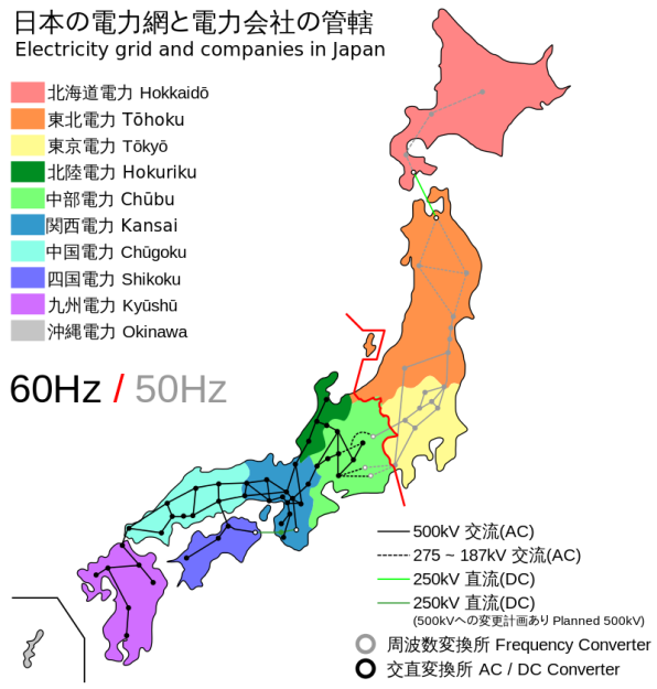 Generally the two system frequencies are isolated to their own independent power grids by large oceans, but there’s one place in particular where the two have mixed. Japan has a 50 Hz grid in the north half of the island, including Hokkaido and Tokyo, and a 60 Hz grid in the southern half which includes Osaka. Early in the electrification of Japan, the northern half bought generators from a European 50 Hz source while the southern half bought generators from an American 60 Hz source. At the time the two areas were far enough apart that interconnecting the two grids wasn’t considered, but now the two are tied together using huge DC converter stations which is the only possible way to connect two incompatible system frequencies.
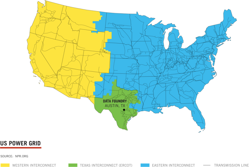
While Japan has two grids separated by frequency by way of a historic quirk, the grid in North America is even more complicated. There are actually three separate grids even though they all operate on 60 Hz, since even if the system frequency is the same the waves themselves have to be synchronized to each other. The two largest ones split the continent in half by east and west. The third is Texas. They are a separate grid essentially as a way for that state to get around federal regulations for energy that is transported across state lines which (in a roundabout way) is related to how much oil Texas produces. The system arose in the 1930s and has continued on to today. Like the grids of Japan, however, the Texas grid is connected to the others by means of several large DC converter stations, so they aren’t exactly an island. While the separation helps them avoid federal regulations, it also grants them some isolation and immunity from blackouts that may occur on other grids, while still being able to import and export power to other companies in other states.
Whatever the reason, this is the system we have now. There are many electrical grids across the world, and even within countries and states themselves. Even if you are reading this from a laptop powered by a solar cell and a battery, you’re on one of the smaller electrical grids around. Indeed some grids are very large, some are small, some have different frequencies, but they all serve one purpose: to deliver energy as efficiently as possible.


As a final irony of history, DC for long distance is coming back as HVDC…
source ?
the transport losses get worse with higher DC voltages.
There is a good wikipedia article on it. It’s in use for quite long distances.
https://en.wikipedia.org/wiki/High-voltage_direct_current
If I may ask.
Why would the losses in a DC system increase with voltage?
Leakage is one thing, but that effects AC as well.
The only other loses I can see is the following:
1. Skin effect losses, this would be there if there is ever any quick change in current demand. (As that is DC biased AC (Without polarity change)) But the Skin effect is far larger problem for AC.
2. Current losses, though, this decreases with an increase in voltage when supplying the same power.
3. Capacitive coupling, though, as we do not have a large change in voltage on an ideal DC system, or even a practical one. Unlike AC where we change polarity, and therefor have 200% voltage change.
Non of there three would be worse for higher DC voltages.
So I’m curious to why would the losses get worse?
If the idea is that high power AC transformers are more efficient then DC-DC transformers, then that is something one could debate for hours. And honestly, I wouldn’t be surprised if DC-DC transformers are more efficient in the end. If one would build a bank of them in some serial configuration, so that each unit don’t need to see the full voltage.
Maybe he wanted to point out that 1. switching the DC becomes harder at higher voltages (costlier equipment needed, how much is an SCR for 1 million volts?) 2. DC switches/contacts are known to last much shorter than AC ones, because there is no null crossing and full current is always switched 3. DC is really cost effective only on longer runs, because it avoids capacitive and inductive effects which then become prevalent 4. in some applications AC might be preferred because it does not cause galvanic corrosion of dissimilar metal junctions.
Actually, AC is worse at long distances than DC, all other things being equal. The wires of a transmission line form a capacitor, and while with DC this only has to be charged once at power-up, with AC it is continually charged, discharged, charged in with the other polarity, at 60 (or 50) Hz. As the line gets longer and longer, this capacitor gets bigger and bigger, and you eventually get to the point where the current required to charge the capacitor meets the current rating of the conductors at the input end. At that point, you cannot actually draw any current out of the transmission line without exceeding the current capacity. AC lines have inductive banks at various distances to cancel out this capacitance.
The DC line has zero capacitive loss only for linear loads. When you have a huge thyristor bank switching the line back to AC, you get a pulsating load down the line and a ripple to your DC which goes through the capacitance and inductance of the line and leaks everywhere.
The problem with the AC lines is that your conductor approaches a significant fraction of the wavelenght of your AC frequency and the whole line becomes a huge radio antenna, pumping out Megawatts of ELF transmissions.
It’s a inherently more complex system compared to “dumb” iron and copper, so it’ll never replace transformers fully.
But it’ll probably find its use in transporting huge amounts of electrical power between two destinations.
Simple large iron and copper transformers are rather complex to build to start with.
Making a DC-DC system is also complex, but not in construction, but rather in development.
And honestly, one could just build a series of isolated DC-DC supplies and connect them in series. Their isolation voltage would on the other hand need to be tens of kilovolts or more in some applications.
Each of these units would be rather cheap and comparably easy to build and making sure they perform with higher then 90% efficiency would not require to much work. And for those thinking that a DC-DC transformer isn’t having peak efficiency over their full output range, that can be solved by having multiple converters in parallel. and switching them on when needed. Also providing a backup if one breaks, so no more single point of failure. (Not that large transformers on most grids are alone to start with, and they usually have a backup if they are critical in the grid)
I’l think I’ll go and design some system and make open source in the future…
It would still be a pulsed or AC hybrid system, as unless you want to use huge resisters, DC-DC power supplies use ac and or pulsed DC. Capacitors would have to also be prevalent, so cost and reliability would be an issue. Ac is perfect for “to house” transmission, and DC is good for most localized loads and small generation(to later be changed to AC). Since small switching power supplies are now prevalent and cheap the market most likely will never change from this.
Hight voltage AC/DC/AC converters actually use a large number of semiconductors in series, often with an optical connection for driving the on/of signal, to prevent voltage issues in the driver.
The cost in any long distance connection is mainly in the cable. For insulated cable (and any cable on see floors must be insulated) the cost is mainly in the insulation and outside protection, and the mass of the protective layer depends on the thickness of the insulating layer. Many thin layers of paper, drenched in oil is still a common insulator in HVDC cables, because as long as the oil is free from any water traces, it can withstand a much higher voltage than any type of plastic, so the insulation can be thinner and the outer protection layers smaller.
AC has a very high peak voltage, and zero voltage 100 or 120 times per second. The cable has to be designed for the peak voltage. DC cables are constantly very close to there peak voltage, so can transmit more energy for the same peak voltage and therefore same cable cost.
The cost of the conversions and any cable losses are insignificant compared to the cable cost, which is mostly based on the designed peak voltage.
video about fixing the paper isolator on a see-floor HVDC cable: https://youtu.be/koNQR2aZBBk
Classical HVDC systems used mercury arc valves (later thyristor stacks) with the destination grid being reinforced by current supplied through the valves. Voltage was controlled by the grid itself and current could be adjusted by delaying the time from zero crossing for the valves to activate (the firing angle).
Harmonics are certainly a concern, but all converter stations are typically equipped with yards of filtration and power factor compensation gear. This usually comprises a significant fraction of project investment.
Modern power electronics provide the ability to generate full scale sine wave outputs with independent voltage control. Most vendors’ independently commutated systems generate an output voltage with high frequency PWM fed through smoothing circuitry and a coupling transformer, but Siemens uses multilevel switches (they call them MMCs) to directly output a good quality sine wave somewhat like a giant PCM DAC. Their system very much resembles the concept you’ve outlined.
The 1420 km Cahora Bassa transmission line that transmits energy from the Cahora Bassa hydro-electric scheme in Mozambique to South Africa uses HVDC and solid state rectification. The DC lines are 1 km apart.
https://en.wikipedia.org/wiki/Cahora_Bassa_(HVDC)
https://www.texastribune.org/2011/02/08/texplainer-why-does-texas-have-its-own-power-grid/
For something that basically grew by accretion, the electric power grid is a monument to human ingenuity. What is somewhat of a issue is the distorting commercial operations that are carried out on it which is putting wholly unnecessary strains on the system to satisfy political ends.
“the distorting commercial operations that are carried out on it which is putting wholly unnecessary strains on the system to satisfy political ends” — arguably also a monument to human ingenuity!
You can clearly see the three US grids on this:
http://fnetpublic.utk.edu/gradientmap.html
It is a good way to while away a bit of free time watching the loads vary and the power transfer between the systems.
That’s kind of cool.
Thanks for the link. It’s also cool that Va Tech is working with UT on this project.
Looks like its overloaded… heh.
Similar info for UK but not as interesting to watch:
http://www.gridwatch.templar.co.uk/
EU freq: http://www.mainsfrequency.com/
UK freq: http://www.dynamicdemand.co.uk/grid.htm#
Brilliant – thanks for the link John,
I live in Australia where its claimed we have the largest interconnected grid along the
eastern coast – well in terms of land area, not raw capacity, guess thats US/Europe.
Some interesting logistics/dynamics re load sharing & where/when/how to inject power
from renewables with appropriate safeguards…
Cheers
I’m waiting for the world to convert to 100 Hz because bla bla Metric System. :P
Maybe we can get 800 comments on the relative merits of 50 and 60 Hz power, and opinions on how 100 Hz would be the best thing since sliced bread or the worst thing since Hitler.
You mean convert to 100π rad/s grid, surely?
Only for the cgs system.
We could go to 400hz like they used in submarines and planes. Such a horrid noise though.
400 Hz is used in aviation as well as marine power because it keeps inductive elements small among other things but the losses with distance as the line frequency goes up precludes using it on the grid.
Fun fact for the frequency discussion: the railway system in some European countries, for example Germany and Norway, does have its own independent grid—at nominally 16 2/3 Hz. (https://en.wikipedia.org/wiki/Railway_electrification_system).
Again, this is not a mere path dependency (arbitrary design decisions frozen by economic inertia) but the frequency range was based on more fundamental reasons due to the technology available at the time.
The basic design choices of the power grid (AC/DC, frequencies, voltages) are still pretty good under the currently available technology. This was by no means a given. The only thing that I have on the radar that could fundamentally change the picture would be the invention of low cost ambient temperature superconductors with high critical current density.
If you watch it for a while you can sometimes see the East coast generation kick up a step and watch the frequency pull back spreading across the states. Occasionally you will see the Texan feed which is at the northern tip of Texas, feeding into the Eastern grid.
Also: this is why 25, 29.97, 30, etc are framerates in film.
29.97 has to do with the scanning of the electron gun across the screen. Check Wiki on that one for details! :D
24 fps is film (you know the clear stuff they used to project light through) the rates you are referring to are for old school video which was based on mains frequency/2 which was a free stable clock for scanning crt. back in the day of vacuum tubes when TV standards were first developed. 30 fps NTSC – 25 fps PAL and SECAM.
And 29.97 is close enough to 30 but the math works out better for adding NTSC color to the signal.
Correct, though a more complete answer is to say that the chroma/color information can fit ‘between’ the luma (black and white) sidebands in the NTSC implementation of 29.97. 15750 was the horizontal scanning rate, and was divisible by 30, however you don’t want to also add color on a carrier wave that is directly on one of those sidebands.
NTSC stands for National Television Standards Comity and they were responsible for both Black and white, and color standards.
PAL stands for Phase Alternate Lines, which is specifically a color encoding scheme which was added to the then-unnamed Black and White scheme.
NTSC = Never the same color, PAL = Picture at last, SECAM- why?
Wouldn’t the neutral wire carry “useful energy” in a two-phase system, along with the other two wires?
Like my home has two phase transformer (secondary is setup for 220Vac output, but it’s center tapped with the neutral wire) and current appears to flow through the hot and neutral lines simultaneously. Were appliances only wired across the two ‘hot’ wires with neutral not doing anything, like modern 220Vac appliances?
The “phases” in a house aren’t true phases because they’re both running at the same phase angle. What you really have is a center-tapped transformer that’s 240 across the whole transformer (the two hot legs) and 120 from either hot leg/tap to the center tap/neutral. In a true two-phase system the phases are 180° apart like a three-phase system the phases are 120° apart.
This is EXACTLY 2 phases 180 degrees apart…
There ‘in-phase’ or zero degrees apart. Here we call that a split phase but it’s not here.
The phases in a house are running 180º out of phase. If they were at the same phase angle, there’d be no voltage between them. Any system with phases 180º apart isn’t two phases. That’s a single phase. In the case of your 180º two-phase system, it’s just differential around a neutral. The two phases lines are still a single phase, though. The neutral wire in this case is just a center tap off of a feeder transformer or the generator. This is called split phase. The only advantage this provides over normal single phase is that it gives you two half-voltage legs, and saves 25% of the conductor material in the distribution network. All north american residential power is split phase. The only way a system can be two phase is to have asymmetrical phases around the neutral. 180º is always and only a single phase, regardless of the presence of a neutral.
See also https://en.wikipedia.org/wiki/Split-phase_electric_power
“Phases” that are simply inversions of each other aren’t counted when stating the number of phases. “Two-phase” power would have 90º between the phases. https://en.wikipedia.org/wiki/Two-phase_electric_power
Larger buildings in the U.K. Have multiple phases, and server rooms often have 2 phases for redundant power. But they’re only used as multiple single phases.
3-phase is only used for industrial / engineering tools.
In the US every server room I’ve been in is three phase. That’s what you get from the electric company in commercial buildings. My office building at only 10K sq ft is three phase. Makes for super quiet air conditioning units. Three phase was more complicated, but much nicer, IMHO.
“they all serve one purpose: to deliver energy as efficiently as possible” – this is only really true if you define “efficiently” in a certain way. The grid in general is not an efficient transmitter of energy, in terms of the ratio of joules out to joules in. The only data I’m familiar with is the UK. It’s not a grid with large distances to cover or sparse population to serve. Yet still nearly *two thirds* of the electrical energy delivered to the grid from generating plant doesn’t make it to the end user; it’s written off as conversion, distribution and transmission losses.
Source in case anyone’s interested: https://www.gov.uk/government/uploads/system/uploads/attachment_data/file/552059/Chapter_5_web.pdf
See the diagram on the second page. Five years ago it was fully two thirds lost in the grid, so it’s got better. Still staggeringly bad.
That table calculates losses in a bizarre way: Conversion, Transmission and Distribution Losses is calculated as fuel used (Table 5.5) minus generation (Table 5.5) plus losses (Table 5.1)
Thermal generation efficiency is always going to be capped by Carnot efficiency (around 2/3 iirc) so this is actually quite good.
So, in short, the huge loss here is principally generation losses because its impossible to convert thermal energy to electrical energy.
in fact, what you actually want is here:
5.15 Losses as a proportion of electricity demand in 2015, at 7.7 per cent, were down by 0.3
percentage points on 2014 (8.0 per cent). Losses comprise three components3:
transmission losses (7.4 TWh) from the high voltage transmission system, which represented
about 27 per cent of the losses figure in 2015;
distribution losses (19 TWh), which occur between the gateways to the public supply system’s
network and the customers’ meters, and accounted for about 69 per cent of losses; and
theft or meter fraud (just under 1.0 TWh, around 4 per cent).
“The grid” is pretty efficient. The chart at https://www.gov.uk/government/uploads/system/uploads/attachment_data/file/552059/Chapter_5_web.pdf starts with raw energy input (introduction, paragraph 5.2 states this). The losses primarily happen at the thermal and mechanical stages. The laws of thermodynamics come in to play here with the maximum return when heat (combustion, solar thermal, nuclear, etc) is the start of the process. These losses don’t show as much for sources like solar thermal and geothermal, since no fuel is burned at the point of generation, but, still, they are there, since the net is based on (T(hot)-T(cold))/T(hot) (Carnot efficiency) when mechanical conversion is involved. For non-mechanical generation, similar rules hold, but the efficiencies are lower yet, with present and short-term foreseeable technologies.
Once the conversion to electric has occurred, the losses are much lower. As a rough (very, off the top of my head, rough) number, <50% thermal to electric, 90+% generator to transmission line, then, depending on load balance and other factors, 80-90% transmission line to customer.
No – the losses due to transmission are much, much lower than that! If you look at how that two-thirds-ish figure was calculated you’ll see it also includes the power generation process. So it really only gives you the ratio of delivered energy to the total calorific value of fuel used to produce it (see Table 5.5). Since most thermal power plants are <40% efficient the quoted losses are rather large, but not solely due to transmission. To be fair, I think the diagram in that reference is a highly misleading.
A more representative figure for "Power delivered to the consumer/Power entering the National Grid" would be about 94.5%, i.e. losses of roughly 5.5%… BUT even this figure dominated by the problem of electricity theft! The "technical" losses are even lower. See the following reference:
https://www.ofgem.gov.uk/sites/default/files/docs/2009/05/sohn-overview-of-losses-final-internet-version.pdf
The typical loss in a 375 kV line in the United States is about 4% per 100 miles according to the EIA – can’t find the document right now so I’m going by memory. Most of the electricity generation happens at less than 200 miles from the consumers, and the average loss on the grid is about 6%
The generators on the grid really operate in a bucket chain fashion, where power stations along the line are pushing power from one area to the next. The transmission losses over distance increase dramatically when the local power demand is saturated and the grid has to transmit current directly from A to a distant B skipping all the points in between – which is what happens with wind and solar power because everyone in the same area gets it at the same time.
if that happens with wind and solar you are talking about older dumb energy grids, today in europe smart grids are all the rage.
I’ve always wondered about the wavelength of 60Hz being about 3000 miles. If we had a fully interconnected electric grid there could be some interesting losses and currents arising from two points being interconnected by two paths of lengths differing by a significant portion of a 1/4 wavelength.
That may be one of the reasons for splitting the country into east and west grids.
Actual “grid” topology is only used for local power distribution, which is small enough not to introduce phase shifts. Transmission lines are all point-to-point. There are usually multiple paths from multiple sources to any given substation, these are used for shifting loads and for fault tolerance, but are generally not switched in parallel except momentarily when switching. There are no loops in the transmission system.
Ignore that. Of course there are loops, where multiple generators are supplying power to multiple loads. I can’t believe I wrote that.
No, Those still aren’t loops. More of a long trough with multiple people pouring into and taking out of it.
“””For almost every one of us, we have power lines leading up to our homes, which presumably connect to a power plant somewhere”””
17% IS NOT “almost everyone”.
As usual with HaD articles, accuracy is lost for the benefit of a “fill-up, write as you talk, proof nothing” article …
83 %
Hang on, who’s “us”? You’re saying, what, 17% of people in the Western world, ie most users of the WWW, don’t have mains electricity? That’s an enormous statement to make. I don’t think I’ve met a single person in my life who hasn’t got mains electricity.
No idea what that 17% figure means, but I have known several people who didn’t have mains power delivered to their homes. Cabins in the woods without mains power are fairly common in the U.S. northwest where I live, and there are plenty of people who live in them full-time. The ones I’ve known used a generator, and only ran it for certain times of day, although nowadays I would guess that photovoltaics and storage batteries are becoming more prevalent. Heat is done separately using propane and/or wood.
And why are you bringing up users of the www? How is that relevant? Just the same, HughesNet provides satellite Internet specifically for people who don’t have full utilities available, which includes people not connected to the electric network.
That depends on the definition of “us”. I suspect that almost all readers of hackaday have dwellings connected to mains power.
ehh…
https://energy.gov/sites/prod/files/2014/04/f15/LPTStudyUpdate-040914.pdf
I don’t even like NPR, but:
http://www.infrastructureusa.org/interactive-map-visualizing-the-us-electric-grid/
Useful is the AC-DC-AC bridge map.
How do you synchronize a variety of out-of-sync AC generators? With DC:
http://atlanticwindconnection.com/awc-projects/awc-technology
Remember that I was the one whining about PoE or something similar to be used in households.
To drown in HVDC propaganda by a company that makes products for utilities:
http://new.abb.com/about/hvdc-grid
On this blog there’s a nice hackaday type of an article related to the subject.
http://jorisvr.nl/article/grid-frequency
Nice. That reminded me of one winter…
The power went out for several days but we have a backup generator for situations like that. I’m kinda OCD about clocks so of course they all were set to an accuracy of seconds to each other…
The next day the oven and microwave clock were off by several minutes and I HaD to look it up on Wikipedia.
The Netherlands has been using a HVDC cable connection to Norway since 2008. The advantage of HVDC for undersea cabling is that the losses are much lower. This is caused by the fact that it costs a lot of power to charge/discharge the capacitance of these highly insulated cables when used for AC.
The cable is used to either import extra power from Norway, or to export excess power available from power plants in the Netherlands to Norway isused to fill enormous artificial lakes. When needed, these lakes are drained through turbines/generators again, providing power back to the Netherlands.
The efficiency of this system is much higher then it would be using battery technology, and can be used on a much larger scale.
During the first 8 months 3000GWh was imported and 330GWh exported.
And in the late 40’s California switched from 50 to 60 Hz.
Most thing went smoothly, but clocks all had to be fixed.
And during that time period, a man named Don Leslie was converting 50Hz Hammond Organs to 60Hz in California which funded his idea to make a better speaker for the Hammond Organ: Without the Leslie speaker, rock and roll would arguable sound a bit different.
nary a comment about Henry Warren and how the line frequency is used for time keeping ?
https://en.wikipedia.org/wiki/Telechron#Henry_Warren:_the_Synchronous_Motor_and_the_Master_Clock
Parts of upstate NY surrounding Buffalo had 25 Hz power till 2006 (!!). This was mostly due to the first generating equipment installed at Niagara Falls which was 12 pole generators running at 250RPM. A lot of industry up there was built around the 25 Hz power so it remained available as an option until very recently, even though the generation equipment had long since been converted to 60 Hz. Conversion from 25Hz to 60Hz began in 1930, but 60Hz load did not exceed 25Hz load until 1952.
Wasn’t that because of Tesla’s first AC power station ?
60 hertz is 377 radians per second.
The intrinsic impedance of free space is 377 ohms.
Now you know the rest of the story
I do? Thank goodness!
“we settled on a three-phase system because it delivers the most cost-effective amount of energy per wire” is not necessarily true. Multiple phases (>2) was mostly chosen to reduce stress on the generator’s shaft: it will level fluctuating power resulting in less fluctuating torque on the shaft. For the sake of simplicity & compromise 3 phases was chosen.
(https://fr.wikipedia.org/wiki/Courant_triphas%C3%A9#Annuler_la_puissance_fluctuante)
The personal grid. That’s the solar panel on your van’s roof putting electricity into your house batteries through a solar controller while you’re sitting in the Arizona desert. The computer gets it’s power from an inverter hooked to the house batteries.
:cough: As nobody else seems to be willing to talk about the elephant in the room…
https://www.cybrary.it/2016/10/power-grid-attack-doomsday-scenario/
http://www.survivopedia.com/power-grid-destruction-of-the-third-and-worst-kind/
After 9/11, I thought about what I would do if I were a terrorist, and I realized that, with enough time and not a lot of money, I could probably be responsible for killing off a quarter of the population of North America by myself. It wouldn’t be hard at all, and, even if I were caught before it was complete, a simple deadman system would trigger what I had already been able to deploy. Chilling, really.
yes, but the fallout from here would travel around the world and kill you in the country you flee to.
think about it, if there are well over 100 places and each one is as bad as chernobyl or fukishima all at the same time you will die no matter where you are on earth, unless earth is not where your fleeing-to
Nah. I read your links, and they basically say that you would need to take out maybe 10 points at the same time. Definitely not a one man job. Big solar storm might do it though.
I really liked how you explained the history of how electricity became what it is today. I think a lot of times we just assume it has always been there. Great job on explaining how commercial grids work!
Since small switching power supplies are now prevalent and cheap the market most likely will never change from this.