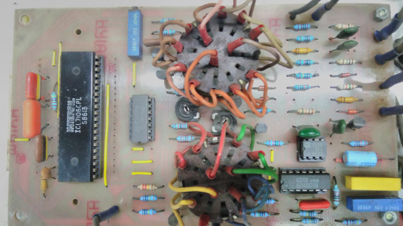
Riffling through my box of old projects, I came upon a project that I had built in the 80’s — an Automotive Multimeter which was published in the Dutch/British Elektor magazine. It could measure low voltage DC, high current DC, resistance, dwell angle, and engine RPM and ran off a single 9V battery. Besides a 555 IC for the dwell and RPM measurement and a couple of CMOS gate chips, the rest of the board is populated by a smattering of passives and a big, 40 pin DIP IC under the 3½ digit LCD display. I dug some more in my box, and came up with another Elektor project from back then — a True RMS digital Wattmeter with a 3½ digit LCD display that could measure up to 2kW. It had the same chip too. Some more digging, and I found a digital panel meter. This had a 7 segment LED display, but the chip was again from the same family.
Look under the hood of any device with a 3½ or 4½ digit, 7 segment, LCD or LED from the ’80’s or ’90’s and you will likely spot this 40-pin DIP with the Intersil logo (although it was later also manufactured by many other fabs; Harris and Maxim among others). The chip doing all the heavy-lifting was likely to be the ICL7106 or ICL7107. These devices were described as high performance, low power, 3½ digit A/D converters containing seven segment decoders, display drivers, voltage reference and clock. In short, everything you needed to take a DC analog signal and display it. Over time, a whole series of devices were spawned:
- 7106 – 3½ digit, 7 segment LCD
- 7107 – 3½ digit, 7 segment LED
- 7116 – 3½ digit, 7 segment LCD, with display HOLD (freeze)
- 7117 – 3½ digit, 7 segment LED, with display HOLD (freeze)
- 7126 – improved 7106
- 7136 – improved 7126
- 7135 – 4½ digit, 7 segment LCD
There were many similar devices available, but the ICL71xx series was by far one of the most popular, due to its easy of use, low parts count and single chip implementation. Here are several parts (linking to PDF datasheets) to illustrate my point: the TC14433/A needed several peripheral devices, ES5107 (a clone of a clone — read below), CA3162 (which has BCD output, and needs the CA3161 or similar to interface to a display), or the AD2020 (which too needed a lot of support circuitry).
The ICL71xx was the go-to device for a reason. Let’s take a look at the engineering and business behind this fascinating chip.
Lawsuit
First, a little bit of history. In 1977, Fluke introduced the model 8020A, their first handheld DMM. Inside it was a chip marked as 429100 — the A/D converter and display driver. This chip was developed by Fluke in collaboration with (the original) Intersil, Inc., founded by Jean Hoerni in 1967 to produce digital watch and calculator microprocessors. A year after the 8020A was launched, Intersil introduced the ICL7106, a clone of the 429100.
To make it functionally different, Intersil masked off the switch that allowed the 429100 to auto-range between 200mV and 2V ranges (which was a Fluke patent). This made the 7106 unsuitable as a direct, drop in replacement for the 429100. But Fluke found out that the silicon inside the 7106 still sported a Fluke logo, and a lawsuit ensued. This was settled out of court, since Fluke could not afford to lose Intersil’s fab facilities. But the 7106 was now available to all for use and would end up inside a large number of products built in those days. You can read [drtaylor] who worked at Fluke during the time reminisce about this over at the EEVblog forum.
Fast forward
If we’re to design a similar product today, the 7106 would definitely be replaced with a micro-controller and a more capable analog front end. And we could choose from a wide range and type of displays running off standard protocols such as SPI or I²C. But the 7106 and others in its range are still available today, almost 40 years after they were first introduced. It seems there may still be a lot of use cases where selecting this device is justified. Especially if the product requires a no-fuss design which doesn’t need to connect to a computer, must be handheld, consume low power, and not require any software calibration.
Under the Hood
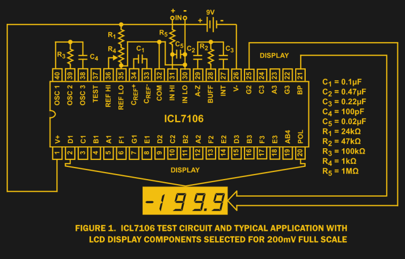
A bunch of passive parts connected to the 7106 is all it takes to build a device running off a 9V battery capable of measuring a ±200mV input. A ±2V range requires some component changes (C2,R2,C3) and adding a divider at the input allows measurement of higher voltages. Calibration can be done using a trimpot (R4+R1) which adjusts the reference voltage to the chip.
The differential inputs and adjustable reference voltage allow sensors such as strain gauges, load cells or similar ratiometric bridge type inputs to be easily interfaced. A lot of these chips got used for weighing scales, for example.
To do what it does, the device uses the “integrating type analog to digital conversion” method — also known as dual slope conversion. This Wiki stub explains the process succinctly. The three part process requires 4000 clock cycles (or 40000 cycles in case of 4½ digit device) — 1000 cycles for auto-zero phase, 1000 cycles for signal integrate phase, and up to 2000 cycles for the de-integrate or reference integrate phase. In order to achieve 50Hz noise rejection, the signal integrate phase needs to be a multiple of 50Hz. For example, to get good rejection of 50Hz, 60Hz, 400Hz and 440Hz noise, the oscillator needs to be at 40kHz and will result in 5 readings every 2 seconds. The oscillator parts (R3, C4), thus, need special selection.
The other parameter that affects performance is the stability of its internal reference voltage. In many cases, a simple voltage divider is connected to the regulated supply rail to derive the reference voltage. But for improved performance, a more stable reference, using a zener diode or a dedicated reference voltage (band gap) device was highly recommended.
The LED versions — 7107 and 7117 — suffered another issue related to the instability of its onboard reference voltage due to self-heating. LED’s consume significantly higher current, compared to LCD’s, and the internal heating that this causes degraded performance a lot. To help counter this, Intersil offered a special device with the “S” suffix, only for the LED versions.
Walking down memory lane is quite fun, especially for parts like this which were hiding in so many kits and products alike. Do you folks have any interesting ICL71xx stories to share in the comments? This article builds on the idea [Jenny List] started with her Get to Know Voltage Regulators with the a 723. If you have a beloved part that would be perfect for this kind of treatment we’d love to hear about it below.


Nice writeup – just nitpicking:
CA3162 and AD2020 are AFAIK the same. Those were known also as C520D (clone manufactured in east Germany) in eastern bloc before 1990.
Another bit of nitpicking. The reason for the Harris logo is that these were originally Harris parts. Later, Harris spun off their semiconductor business and called the new company “Intersill.” Thus “Harris” and “Intersill” parts came out of the same fab. I used to work for Harris over 10 years ago, but I started working there in 2000, after the Intsersill spinoff.
Whoops, never mind. I just read the link on the story of Intersil. I did not know that the name existed long before Harris purchased them…
Intersil was innovative, at a time when things were breaking out. I guess they made some “bread and butter” ICs, but they created niche items, a good number if which stayed around for a long time. So this DVM and the 8038 function generator (I think before Exar got into it, with a wider selection of function generator type ICs), and the frequency counter ICs I mentioned below. They even had the 6100 12bit CMIS CPU in the late seventies, in essence a PDP-8 on an IC. So they stood for those, compared to National that had a wide range of analog ICs.
Michael
Thanks for pointing out CA3162=AD2020 — I guess the text didn’t make it clear. Didn’t know about the C520D, though. Was there a ICL71xx series equivalent in the eastern bloc ?
Yes, Tesla manufactured MHB7106, direct clone of ICL7106. I’m pretty sure there was Soviet clone of ICL7107 or something very similar, I’ve seen construction “abusing” this LED driver ADC to drive LCD in DIY autorange DMM. I can search for it in my paper magazines.
there is КР572ПВ2 which i believe is still in production
I have “a few” of those clones of various western chips (not just ADCs), I thought of taking photos and writing down something about them – some of them do have interesting history – perhaps on my .io page.
We had MRY7906 (ICL7106 replacement) manufactured by ITE (research institute, experimental stuff) for CEMI in Poland under Russian occupation.
Interestingly it wasnt a mask copy ripoff. You can see working chip and decapped die photos here http://www.leon-instruments.pl/2012/04/kolekcja-struktury-ukadow-scalonych-z.html
Also known in the US as NTE2054 (ECG 2054)
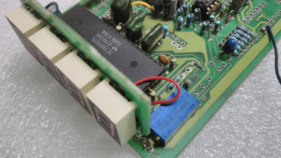
This is the same chip used in Harbor Freight freebee meter. It’s under the black blob.
Shows how cheap it is to be given away for free.
It, or clones of it, or clones of clones of it, are also in pretty much every other cheap 2000 count meter. I recently scrapped an oxygen level meter from the 80s that had seen rather too much oxygen (the PCB was corroded and falling to bits).. inside was a couple of op amps, and a panel meter based on … you guessed it the ICL71XX – no doubt when this thing was originally produced it cost well north of £1000 but as you say, the bare die under those epoxy blobs is so cheap today that they practically give them away.
The 40 pin DIL reminds me, my first hack 30 years ago, reusing the LED clock unit of an 1976 clock radio…
The MM5387AA (clock&driver) needs only!.. 24 to 28 VDC as power supply !!!
I remember :-) I built a clock with this chip in the 1980ies. I was happy becasue I got it quite cheap, but transformer, case, LEDs and stuff made the project more expensive than a ready made radio clock – even without a radio in it.
That was one of my intro to ICs and LEDs too, Not sure if it was a Ramsey Electronics kit or what, came with a circuit board, wall wart, chip(s) wood frame to glue together and red plastic screen. Looked thru my LCD/LED/VFD box and found a VFD board with ICM7235AM clock chip, must …. apply ……. power…….
Nice article Anool.
There is a TheAmpHour episode where they interviewed Dave Taylor (link below) where he tells the story of development of these ICs.
http://theamphour.com/180-an-interview-with-dave-taylor-multi-talented-meter-maker/
They had a great launch. Intersil offered a kit for the basic voltmeter, there was an LED one and I think an LCD one, which I think was more expensive. Memory says I paid around fifty dollars Canadian for the LED kit in the fall of 1978, fining a local distributor that carried it.
The kit was the IC, the readout, the board and the parts for the basic meter. I think it was classed as a “development board”, but it got promotion in hobby circles, either deliberately or because the hobby magazines discovered it. No real assembly instructions, it came with the datasheet and an application note which gave ideas about making a DMM, including autoranging.
On introduction, the kit was a cheap way to get a DVM, though that changed rapidly since the IC did cause lots of commercial DMMs to come to market. And endless articles bout using the IC.
I’m not surprised the IC is still used. The cost of designing the IC has long been paid for, and since it was a good design, what needs improving? So it makes for cheap equipment, I assume scientific calculators are using ICs that are now old.
Don’t forget that Intersil, around the same time, had the 7208 frequency counter IC (and a later one better integrated and better specs) which did the same thing for frequency counters, doing away with endless strings of 7490/7475/7447s, making things smaller and more compact.
Michael
Did you mean the 7216/7226 Frequency Counters ? I remember having used the 7216 to build a freq. counter.
No, the 7208 came first, the 7216 was the later refinement that was better.
The 7208 needed an external time base, Intersil made an IC for that, but you could use something else. I forget what improved with the 7216, but it did improve things.
Michael
I saw these chips in a lot of meters back in the 80s & 90s. Intersil had some awesome chips back then. One of my favorites is still the ICM7226 counter chip. A nearly complete 10 MHz time interval counter in just one chip. Add -at the time- a few 11C90 prescalers and it would do most way to a GHz. You can still get the 7226 from Chinese sources but they are pricey. (More than an entire 2.7 GHz counter module.) MC12080 is about the only /10 prescaler left as well.
Most of the cheap 7106 panelmeter need a supply separated from the measured voltage. Some modules which are supplied by their measuring voltage use a low drop 3V3 regulator and an inverter charge pump to make a negative voltage and probably an external reference.
I modified a panelmeter to display the voltage in a 12V battery system in a different way:
I separated the input (-) from the COM, used a symmetrical voltage divider 1M-200k-1M connected to the input voltage and connected the input across the 200k resistor. For the supply I used a 15V zener diode (which is the max. voltage of the chip) across the supply pins of the 7106 and two resistors of (I think) 220Ohm from the battery + and – to the supply pins.
With this arrangement I am nicely in the middle of the common mode range of the front end and current is passing through the zener diode only if the battery is charging at or near its maximum voltage. Without charging power no current is wasted in the zener diode.
The ICL7106 is a very insightful design, with a detailed explanation of the internal workings not commonly found in modern datasheets. Well worth studying, especially the analog section.
http://www.intersil.com/content/dam/Intersil/documents/icl7/icl7106-07-07s.pdf
http://pdf.eicom.ru/datasheets/intersil_pdfs/icl7106_07_07s/ICL7106_07_07S00007im.jpg
I just checked my inventory list,
I have (9) ICL7109CPL chips, they are 12 bit ADC, but instead of driving a L[CE]D it drives a data bus for a microprocessor.
We used the Maxim LCD clone (ICM7224) for decades on production gear.
I was told that it originated with the designer building an echo sounder for his boat which used the 7224 to display depth under the keel – he just adapted the design of the input stage for use in our telecom product…
The Fluke 8060A’s and their relatives used the Intersil chips with silver-plated leads. I’ve fixed a number of these “dead” meters by removing the chip, cleaning the tarnish off of the IC leads with an eraser and replacing them. I still have a couple of these and they work great after many years of service. It’s a testament to Fluke and Intersil’s designs. Very well designed meters!
I have bought the elektor kit way back in the 90’s but never got to assemble it. Its based on 7106 LCD driver. I lost the circuit diagram and the article that came with it. The LCD has also faded with age. I now wish to revisit the kit with a IC 7107 that I salvages from another display. If anyone in this forum has the article saved, please share the same.
I think some of the readers of this topic may be interested in my ESP32-controlled TCL7135 project.
https://www.elektormagazine.com/labs/esp32-digital-voltmeter
Again, years late to the party…
I worked at a place in the early 1980’s that built stuff for people, a job shop. One thing we had was building the electronics to move the big old satellite dishes. These were set top boxes with a 10 position switch for memories and up and down buttons for tweaking or looking for things that were not programmed. They were analog servos. Out at the disk there was a DC motor and a 10 turn pot for feedback. The motor was driven by a pre fab board that looked like it was out of a blender. It did do current sensing. It was surrounded by a pair of big relays. One to click in in and out and one to reverse the polarity. The part that I used to swipe for all of the other test fixtures etc that I built though was the 0-2V meter they used to display the position. They had been building these things for years before I came along but I was the first person to use one of the meters “out of the box”. They caught on like wildfire. We used a lot of them for assorted stuff. I had one job where I had to watch the output of a 400hz power supply that I also built, and use a germanium diode bridge so it could read AC. It was surprisingly accurate above about a half volt. These meters used a pair of RCA chips I believe, one did all the analog stuff and one did the display driving.
I had not pondered those in years. I am just getting into playing with some remote powered solar gear and thinking how handy it would be to have a bunch of them on hand again. Back in the day they were “free”, now to have to spend over 17 bucks to get 10 of them. But now they have neat blue displays…
The overall list is missing MAX 7137 – improved 7117 and 7107