Meticulous. Thorough. Exacting. These are all words we’d use to describe this video by [BrendaEM] about her Homemade 3D Optical Interference Scanner which can be seen after the break. The scanner uses 3D-printed parts and repurposed materials you might find lying around in your spare parts bin. An old optical drive tray acts to move the laser-wielding sled while a stripped-out webcam is an optical sensor. Links to relevant files such as 3D models and Arduino sketches will be found in the video’s author section.
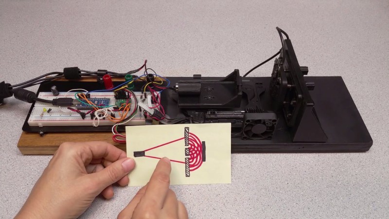
The principle of operation is demonstrated with a water analog in the video at 2:00 with waves in a plastic container. By creating two small apertures between a light source and a sensor, it’s possible to measure the light waves which make it through. [BrendaEM] uses some powerful visualization software to convert her samples into 3D models which look really cool and simultaneously demonstrate the wave nature of light.
On the left side of her device are the control electronics which don’t need any special coatings since light won’t pass over this area. For the right side, where coherent light is measured, to borrow a Rolling Stones lyric: no colors anymore, I want them to turn black. Even the brass strips with apertures are chemically darkened.
Most of the laser hacks here use lasers rather than measure them, like this Laser Clock and a Laser Projector.


Nice build!
What did you use for painting everything black? how conductive was it electrically and thermally? did any of the parts like webcam electronics suffer from this?
In most textbooks interference is depicted as 2 slits with parallel rays which then interfere at infinity, in such a small setup, did you consider using a lens (perhaps simply the original webcam unit as a whole) to transform parallel rays to pixel positions?
Hi,
Thank you.
I used 99-cent Home depot flat black enamel for most things. Anything that gets wear, I use lacquer.
Optimally, I would would want a spatial filter, and a beam expander. The problem is, out in the garage, I find it difficult to keep things clean. The other problem is: everything adds reflection.
The beam from most laser diodes is quite astigmatic, too.
Great job.
It may be worth pointing out that the observed rings are not the result of interference by the two pinholes, but difraction of each pinhole individually. The pattern is two overlaped airy disks.
https://en.wikipedia.org/wiki/Airy_disk
The vertical lines she mentions from around 57:50 *are* the result of interference of light through both pinholes. They are not an artifact of the sensor.
Hi Strayphoton,
Yes we do have 2 airy disks, but we do have interference between them, as evident in the 2nd video, as dissociated blobs.
For a better view: https://upload.wikimedia.org/wikipedia/commons/5/5f/3D_Interference_of_Laser_Light_Through_2_Pinholes_Animation.webm
If you have some information about the vertical lines, please post it. The vertical lines I mention appear to line up with nth of pixel boundaries. If stop the animation at various places, the appear to line up regardless of z-depth.
Hi Brenda,
Indeed the Airy patterns interfere, what I point out (for any readers not familiar with optics) is that the ring patterns themselves are not the result of interference between the two pinholes.
The overall pattern is the result of diffraction (also a form of interference itself) of each hole (circular hole -> Airy pattern) and interference of two identical sources , two holes in this case (-> blobs in Airy pattern overlap *and* the fringes everywhere).
From screen captures I estimated the number of fringes you should expect in between Airy disks given the size of the latter and it seemed to make sense. Rather than elaborate it here though, when it may well be wrong, you could perhaps test that a single pinhole will result in no fringes at all, only the Airy pattern.
“Rather than me elaborating it here” , I meant.
Alternatively, you could rotate the image sensor something like 45 degrees and see if the ‘vertical’ lines rotated as well. If it was caused by a sensor issue you would expect the orientation of the lines to change.
https://en.wikipedia.org/wiki/Bayer_filter
That might be the reason for the vertical lines.
Editor,
Thanks again for such a great write up : )
This was a very important little project to me, that admittedly, I’ve worked 4 years on, with a few month push to get it done.
It was my pleasure to look over such a labor of love. Nicely done, BrendaEM.
Nice build. I guess the vertical lines are from the cover glas of the sensor. I have been working in Interferometry for many years and fringes like those are a typical effect that you can see when the ghost reflex of the cover glas interferes with the direct passing wavefront. Therefore in interferometry the cover glas is typically removed.
I have also worked with cameras without cover glas outside the clean room and it wasn’t really a problem. If you’re using a cheap webcam sensor i would give it a try removing it.
Thank you : )
Only after a friend donated a binocular microscope, did I realize why I ruined two sensors. The cover-glass bezel on the c905 webcam is very weak, and when I tried to pry up against it, my needle sunk through it, and skated across what was the sensor.
For the unobtainium build, I have a wafer inspection linear translation mechanism, which will have .001mm steps. When I get that going, I will make another attempt at the cover glass.
Eight-bit Webcam sensors do not have enough dynamic range for this kind of study. Sigh.
–Brenda
Great do you think this could apply in a bigger projection?? its amazing job!!