Coin Cells: The Mythical Milliamp-Hour

Just how much metaphorical juice is in a coin cell battery? It turns out that this seemingly simple question is impossible to answer — at least without a lot of additional information. The problem is that the total usable energy in a battery depends on how you try to get that energy out, and that is especially true of coin cells.

Energizer specs its 2032s at 0.2 mA

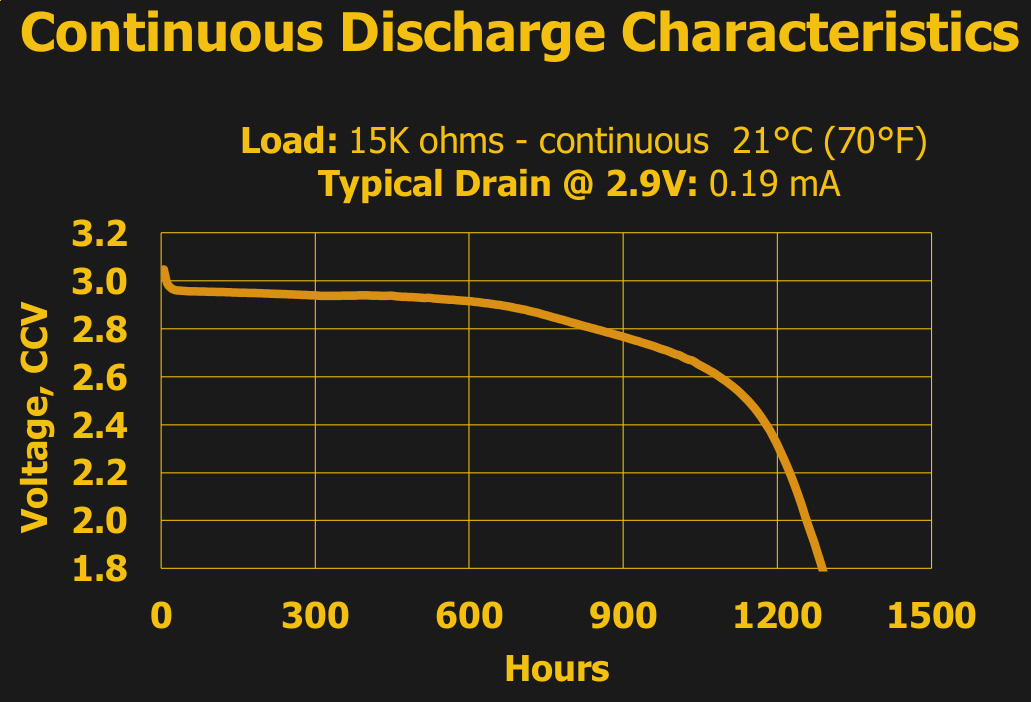
For instance, ask any manufacturer of the common 3 V lithium 2032 batteries, and they’ll tell you that it’s got 230 mAh. That figure is essentially constant across brands and across individual cells, and if you pull a constant 0.2 mA from the battery, at room temperature and pressure, you’ll get a bit more than the expected 1,150 hours before it dips below the arbitrary voltage threshold of 2.0 V. Just as it says on the tin.

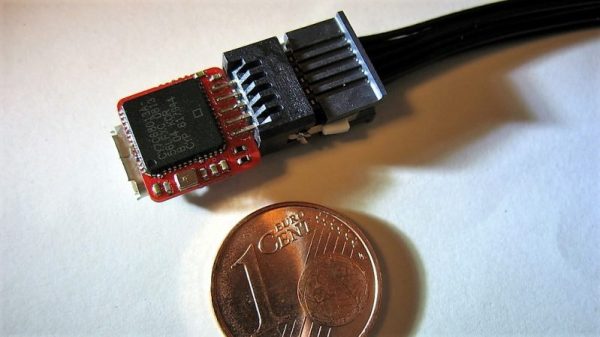
What if you want to do anything else with a coin cell? Run an LED for a decade? Pull all the energy out right now and attempt to start a car? We had these sorts of extreme antics in mind when we created the Coin Cell Challenge, but even if you just want to do something mundane like run a low-power radio sensor node for more than a day, you’re going to need to learn something about the way coin cells behave in the real world. And to do that, you’re going to need to get beyond the milliamp hour rating. Let’s see how deep this rabbit hole goes.

Continue reading “Coin Cells: The Mythical Milliamp-Hour”

Improving Cheap Laser Engravers For PCB Fabrication

A few months ago, [Marco] picked up a cheap, cheap, cheap laser engraver from one of the familiar Chinese resellers. It’s a simple affair with aluminum extrusions, a diode laser, and a control board that seems like it was taken from a 3D printer controller designed five years ago. Now, [Marko] is building some upgrades for this engraver and his PCB production skills have gone through the roof.

The laser engraver [Marko] picked up is called the EleksMaker, and lucky for him there are quite a few upgrades available on Thingiverse. He found two 3D printable parts, one that keeps the belt parallel to the aluminum extrusion, and another that provides adjustable x-axis tightness on the belt. With these two mods combined, [Marko] actually has a nice, smooth motion platform that’s more precise and makes better engravings.

These upgrades weren’t all 3D-printable; [Marko] also got his hands on a few Trinamic TMC2130 stepper motor drivers. These stepper drivers are the new hotness in 3D printing and other desktop CNC machines, and looking at the waveform in an oscilloscope, it’s easy to see why. These drivers produce a perfectly smooth waveform via interpreted microstepping, and they’re almost silent in operation. That’s terrible if you want to build a CNC chiptune player, but great if you want smooth engraving on a piece of copper clad board.

This project has come a long way since the last time we took a look at it a few months ago, and the results just keep getting better. [Marko] is making real PCBs with a laser engraver that cost less than $200, and the upgrades he’s already put into it don’t add up to much, either. You can take a look at [Marko]’s progress in the video below.

Thanks [dechemist] for the tip.

Continue reading “Improving Cheap Laser Engravers For PCB Fabrication”

Logic Analyzer Pushes The Limits Of Miniaturization

Careful not to sneeze while using this diminutive logic analyzer — you could send it flying across the bench.

Undertaken more for the challenge than as a practical bench tool, [Uwe Hermann]’s tiny logic analyzer is an object lesson on getting a usable circuit as small as possible. Sure, some sacrifices had to be made; it’s only an eight-channel instrument without any kind of input protection at all, and lacks niceties like an EEPROM. But that allows it to fit on a mere 11 x 11-mm fleck of PCB. That’s a pretty impressive feat of miniaturization, given that the Cypress microcontroller running the show is in QFN package that takes up 64-mm² all by itself. A micro-USB connector takes up much of the back side of the board and allows the analyzer to talk to sigrok, an open-source signal analysis suite.

Everything about the project is totally open, including the PCB files, so you can build your own if you feel up to the challenge. We’d strongly suggest you check out this primer on logic analyzers first, though, especially since it focuses on the capabilities of the sigrok suite.