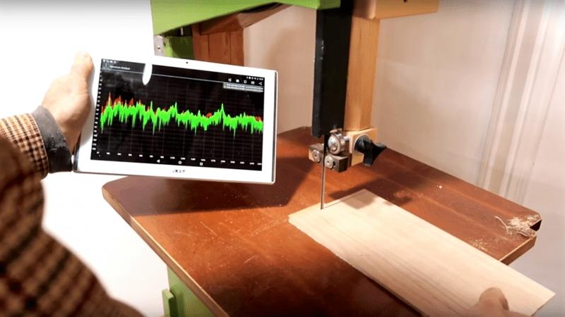
It’s the latest in instrumentation for the well-appointed shop — an acoustically coupled fast Fourier transform tachometer. Sounds expensive, but it’s really just using a smartphone spectrum analyzer app to indirectly measure tool speeds. And it looks like it could be incredibly handy.
Normally, non-contact tachometers are optically coupled, using photoreceptors to measure light flashing off of a shaft or a tool. But that requires a clear view of the machine, often putting hands far too close to the danger zone. [Matthias Wandel]’s method doesn’t require line of sight because it relies on a cheap spectrum analyzer app to listen to a machine’s sound. The software displays peaks at various frequencies, and with a little analysis and some simple math, the shaft speed of the machine can be determined. [Matthias] explains how to exclude harmonics, where to find power line hum, isolating commutator artifacts, and how to do all the calculations. You’ll need to know a little about your tooling to get the right RPM, and obviously you’ll be limited by the audio frequency response of your phone or tablet. But we think this is a great tip.
[Matthias] is no stranger to shop innovations and putting technology to work in simple but elegant ways. We wonder if spectrum analysis could be used to find harmonics and help with his vibration damping solution for a contractor table saw.
Thanks to [Itay Ramot] for the tip.


I downloaded a free app called Giri that does the same thing – except it actually gives you an RPM readout. No idea how accurate it is, haven’t put a physical tach on anything I’ve measured with it.
“* Please measure in a state of only motor sound, for example remove the gear.
* Please measure as close to the motor microphone.”
finally a use for that click when the weld on your bandsaw blade passes the guides every revolution :)
And use a guitar tuner app to check the tension of the blade!
Bearing noise.
From an experienced vibration analyst….yes, this *can* work, but a “simple, quick” measurement can very easily lead you astray. If you know how many teeth are on the saw blade, how many vanes are on the pump, how many rotor bars are in the motor, etc, picking out shaft rate may not be too difficult. But the less you know about a machine, the easier it is to be fooled. What you think is rotation rate may in fact be 2x rotation rate, caused by misalignment. Or, if a machine has journal bearings, that “rotation rate” may be 40 – 50% of running speed, caused by excessive clearance and oil whirl.
Yes, the technique can work and it’s virtually free to try it…but use caution in what you think you know.
This, absolutely.
But on the other side of the coin, a digital recording at idle, plus the spectrometer in VLC helped me make the distinction between piston slap (at engine RPM; engine rebuild) and valve lifter noise (half engine RPM; flush & change the oil you idiot).
What a happy oil change.
Don’t forget the sawdust!
Oh, wait, that is for transmissions, differentials, and transfer cases…
B^)
Wait, what? I thought that was banana peels :D
Piston slap… Subaru?
2002 Jeep TJ (Wrangler), with the inline 6. They had two problems that year that gave you a ticking noise – valve lifters and (defective) piston failures. So far so good.
Now for an app that will strobe the camera flash LED and check RPM through the camera.
I was hoping it would measure deviations in 802.11 reception : )
Didn’t AvE mention this in his Viejo, but just to use audacity for FFT ?
I kept thinking he was going to cut the tablet in half every time he brought it near the table saw.
Fun video, and that guy has some good wood working videos!
I quite like this technique.
I wonder how long the spy agencies have been using it.
Ever since the FFT was invented. :-p
For a while I have been “planning to think” about hacking together an optical tach using the IR sensor from a mouse wheel, an arduino, some code and a PC (to estimate the gear ratio I would need for another hack I’m planning to think about)
And THIS is so obvious … (after someone else points it out)
Not very portable if it needs an extra PC. The simple calculations for gear ratio (n:m) are easily done on the MCU itself.
Been there, done that ;)
http://forums.tdiclub.com/showthread.php?t=473932
A few years ago I made an app for Android that did precisely this, you calculate the RPM from sound using spectrum analysis (FFT).
The app is called an acoustic tachometer: https://play.google.com/store/apps/details?id=com.javiery.rpmgauge
For measuring combustion engines rpm there should be a device to pick up the signal from the ignition coil, and send it to a cellphone over bluetooth.
You would get a very exact reliable and responsive reading.
You should be able to couple it directly to the microphone port via a capacitive clamp. Of course you need some input protection, a series resistor and two anti-parallel diodes should work.
anything for less demanding ? Tape a flap to anything rotating . Say your electric drill , Put your finger against it or whatever. record sound > Produce approx rpm from that wave file ???
I would, as a rule, not recommend to put a finger against a rotating part. Use a screwdriver or something. And you do not need to record a wave file when you can do it on the fly.
This is goog app, I measure many trials on many applinces between 50 Hz to 22000 Hz and found correct. but i think commom man can not workout easely on spactrum analysis