As some of my previous work here at Hackaday will attest to, I’m a big fan of World War II technology. Something about going in with wooden airplanes and leaving with jet fighters and space capable rockets has always captivated me. So when one of my lovingly crafted eBay alerts was triggered by something claiming to be a “Navy WWII Range Computer”, it’s safe to say I was interested.
 Not to say I had any idea of what the thing was, mind you. I only knew it looked old and I had to have it. While I eagerly awaited the device to arrive at my doorstep, I tried to do some research on it and came up pretty much empty-handed. As you might imagine, a lot of the technical information for hardware that was developed in the 1940’s hasn’t quite made it to the Internet. Somebody was selling a technical manual that potentially would have covered the function of this device for $100 on another site, but I thought that might be a bit excessive. Besides, where’s the fun in that?
I decided to try to decipher what this device does by a careful examination of the hardware, consultation of what little technical data I could pull up on its individual components, and some modern gear. In the end I think I have a good idea of how it works, but I’d certainly love to hear if there’s anyone out there who might have actually worked with hardware like this and could fill in any blanks.
Overview
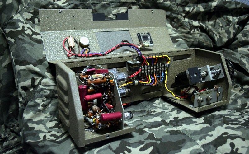
The first thing I was struck with was how big and heavy this thing is. Compared to modern hardware, the CP-142 is built like a literal tank. It’s constructed of thick folded sheet metal with a fascinating crinkle coating of some type that just screams “Old School Military”. It’s roughly the size and shape of a toolbox, with an opening on the bottom that makes me think it was originally intended to straddle some other piece of hardware.
Controls are very minimal: there’s a power switch and “Intensity” dial on the left, and a window to view a mechanical readout on the right which reads “Miles”. On the side of the device there’s a 70mm graduated dial which moves the counter when it’s rotated. It’s immediately clear that rotating the dial is meant to set a specific distance, but more on that later.


After loosening two thumbscrews on the bottom, the CP-142 can be opened up on a hinge to view the internal components. Two clearly labeled fine adjustment knobs near the primary control seem to indicate that opening up the hardware to fiddle with the internals was not uncommon. There’s even a little hex key wired to the frame of the device which can be used to loosen or remove the control dial, likely so the operator could align the marked graduations with the pointer on the front of the case.
Electronics Section
The left hand side of the CP-142 is dedicated to the electronics, which consists of four 12UA7 tubes, a 6AK5, a 6AL5, and a Raytheon UX-7350 transformer. There’s no PCB in this device, all the wiring is done point to point, with a few hard metal “rails”.


Wiring
A thick bundle of wires comes out of the electronics section into a bus bar that’s located right under the lid hinge. There’s also a switch here which cuts power to the device when the lid is opened. Clearly the device would be opened enough that a safety interlock and methods to prevent wire fatigue from repeated opening and closing was deemed necessary.
The bundle of wire is wrapped up with loops of black thread every 10mm or so, which was certainly done by hand. It’s incredible to feel the connection to the manufacturing workforce of the time. In all likelihood, a woman who was part of the labor force who stepped up to support the war effort was tasked with tying these little thread loops around bundles of wires for eight hours a day alongside those workers routing the wires and doing the point-to-point soldering.
Above the bus bar the wiring goes to the power switch, intensity dial, and a bulb which lights the mechanical display. The construction of the switch is something I’ve never seen before, as rather than having a Bakelite body as you’d normally expect from the era (and which is present in other areas of the CP-142), it’s made of sandwiched pieces of some kind of fiberboard.


Dial Assembly
Everything in the CP-142 is a fascinating look at how hardware, and specifically military hardware, was designed 70-odd years ago. But of all the components of this machine, the dial assembly is the most impressive. It takes input from the user, but also provides them with a real-time display of the range currently selected. This is accomplished mechanically, with the counter and dial on the same axle.
A pair of beveled gears are used to connect the axle to a massive potentiometer mounted 90 degrees from the dial. Rotational end-stops are provided by a small section of threaded rod and a little constrained nut that rides it. The nut cannot rotate, so it moves horizontally across the rod as the dial is turned. Once it hits the minimum or maximum travel, precisely machined ledges come into contact, making further rotation impossible.


For you input device aficionados out there, I have to say, the action on this dial is incredible. The dial itself weighs in at 260 grams, and even with all the mechanical movement involved it feels extremely smooth. I’ve spent more time than I care to admit spinning this dial back and forth over the last few days.
Awakening a Sleeping Giant
I’m not sure at what point I decided I wanted to try to power up the CP-142. I kept looking at the red tag attached to the device that says “TESTED OK – 4/6/54” and wondering if a machine that had been in storage for 64 years would still work.
None of the wires were labeled, but documentation for the vacuum tubes was easy enough to come by (the 12AU7 is still used in audio amplifiers), and with a multimeter I could track where everything was going. The bus bar and fastidiously color-coded wiring also helped immensely. I knew what voltages the vacuum tubes wanted, and on which pins they should be getting it. In theory it should just be a matter of plugging the correct voltages into the bus bar and hoping for the best.


I’ll be totally honest, when I saw that display flicker on and those tubes start warming up for the first time in over six decades, it was a pretty incredible moment for me. This is the kind of technology that I’ve always admired, but to have this legitimate piece of history up and running on my bench gave me an opportunity to connect with that era that I’ve never had before.
Operating Theory
Owing to my modern interpretation of the word “computer”, I originally thought that this device would take some kind of signal from the radar and use that to rotate the physical counter. But once I took it apart I realized that the counter was connected to a potentiometer, the value of which was being read by the on-board electronics. Logically, it seems that the electronics must be taking the variable resistance of the potentiometer and turning that into a frequency which the vacuum tubes are amplifying.
On the bottom there are two N type RF connectors, and I reasoned that if I put the oscilloscope on them I should be able to see something happening as I manipulated the controls. One of the connectors didn’t seem to have anything of interest going on, but on the second I saw the confirmation I was looking for:


Final Thoughts
Seeing the oscilloscope come alive after I spun the dial on the CP-142 convinced me that, while I might not have everything 100% correct about this particular piece of vintage wartime tech, I must be pretty close. There are still some questions, of course. What does the radar do with this signal? What does the second RF connector do?
In any event, I’m satisfied with the amount of knowledge I’ve gained about the CP-142. Usually at this point in a teardown I would start thinking of how I could salvage parts from the device, but in this case it doesn’t seem appropriate. Even if that dial assembly is just an Arduino away from being an awesome USB input device, this veteran will be enjoying the rest of its retirement on a shelf in my office. We’ve got history together.


Good Lord that input device is a beauty. I recently dismantled and fixed an old Sansui amplifier, and I love the sheer mechanical loveliness behind all the pots. Another thing about that old circuitry: every board had all the traces silk-screened on both sides, so you could trace and decipher the board from any angle. I really appreciated that.
I remember fixing a Sansui tape deck from the mid 70s… and remember things like that being marked out on the PCB silkscreen too. Of course the problem I was chasing was mechanical in nature; the belts had perished, but I remember spinning the flywheel by hand and pressing buttons on the mechanism to watch how it all worked and being mesmerised.
That also told me why I was seeing the behaviour I was seeing with the belts in the condition they were. A trip to the grinning glasses for a packet of assorted VCR belts (can’t even buy a VCR from them now Kogan own them now) and I had the replacements in and the deck working 100% again.
Grinning glasses?
Dick Smith Electronics I would guess.
https://upload.wikimedia.org/wikipedia/commons/thumb/f/fc/Dick_Smith_Electronics.jpg/590px-Dick_Smith_Electronics.jpg
That potentiometer is evidence that The Borg have visited us in the past!
B^)
Specifically George W. Borg – yes, the collective has a first name. Followed in 1958 by the Amphenol-Borg and several other merger/divestitures. I’ll let you create the rest of the story-arc leading to cubes in space.
http://www.borggeneral.com/about-borg-general.html
Resistance is Variable
A+ comment
Perfect
made my day
And look at the linearity tolerance spec on the name-plate on the side of the pot: 0.1%. The overall resistance might well be less accurate, but in this application, it’s the linearity that counts.
What a beautiful piece of hardware.
The term you’ll want to have handy for the thread you see there is “cable lacing”. I read about this a long time ago via this article: https://makezine.com/2009/07/28/lost-knowledge-cable-lacing/
I was wondering if it was “laced” or individual ties. I didn’t see any string connecting the ties together (in the photo).
Nowadays, it would be “laced” but maybe the military had different ideas back then.
I’ve seen lacing in equipment almost that old.
Expand the photo, it’s definitely a continuous string done in the same style. Easiest to see in the first close-up of the wiring, bottom left.
So that’s what that is called! Thank you. I’ve seen nary a few pieces of hardware done up like that, always loved the way it looks. I’d like to try it myself someday.
Back in the 1970’s I had the opportunity to work with a man who built professional audio consoles. Some of them were developed specifically for the Voice Of America radio stations. Much of his work used transistorized circuits enclosed in metal shielded packages that looked like metal vacuum tubes. They were made by a company named “OpAmp Labs”. Anyway, he wired the audio circuits using the lacing tape mentioned here. Normally the wiring was all designed and built using a large sheet of plywood with nails or terminal strips. Each wire of proper color and size was laid out on the board and spade lugs would be crimped on the wires that needed them. The ends of each wire had pieces of numbered tape wrapped around them for identification. The entire harness was then laced on the plywood board. The completed harness was then lifted off the board and dropped into the final enclosure. Wires were exactly where they needed to terminate and were soldered to the sockets or other components. You can think of the harness as a flexible 3D “circuit board”. Working there was a great experience.
Most UK telephone exchanges were entirely laced like that for decades, it’s frickin’ amazing to stand in front of a wall of 10,000 connections all beautifully laced out across the backs of panels.
Wiring standards was also covered here on HaD in an article by Brian recently
https://hackaday.com/2018/01/12/bradley-gawthrop-what-you-need-to-know-about-wiring/
and from there the link through to the NASA guide which includes cable lacing (from p28 onwards)
https://standards.nasa.gov/standard/nasa/nasa-std-87394
They still do this with aircraft wiring to keep it organized, tight, and reduce weight.
There’s a specific way of doing the lacing (not surprising on military gear..).
I worked a summer job lacing cables on temperature compensation daughter-boards in military field radios.
Had to redo quite a few because the lacing wasn’t to spec..
a quick search for “WWII “range computer”” brings up this link:
https://en.wikipedia.org/wiki/Reeves_AN/MSQ-77_Bomb_Directing_Central
quote:
“The plots were of tracks calculated by the computer’s Aircraft Coordinates and Plotting Group which converted radar spherical data to plotting board cartesian coordinates (non-inertial east, north, up coordinate system) using sine/cosine voltages and radar-estimated range respectively from the Antenna Group (azimuth/elevation resolvers) and from the Track Range Computer. Additional A/C Coordinates amplifiers computed the velocity components (not plotted) which along with the track position components were provided as initial bomb conditions to the ballistic computer (Bomb Trajectory Group).”
As these were used in the Vietnam War, I guess the principles are very similar.
So my best guess is, that you see the mentioned “sine/cosine voltages” for plotting something on a plotting board.
Maybe some additional data-feed is needed to tell the device which direction is to be calculated (through the second RF connector?).
Just my 2ct.
BTW, sine/cosine voltage likely refers to the output of a position encoder called a resolver ( https://en.wikipedia.org/wiki/Resolver_(electrical) ), or to a signal simulating a resolver. They are/were commonly used in aircraft and military systems.
In the Air Force in the 1970s, I worked on RADAR equipment designed in the 50s and 60s that used resolvers to encode antenna azimuth and elevation angles. These were rotary transformers that worked way better than potentiometers, because they didn’t have wipers to wear out, and since they were sine/cosine transformers, they produced AC signals that could be amplified by simpler circuits than DC signals. In those days, a DC-coupled amplifier with low offset had to be chopper stabilized (essentially converting the signal from DC to AC, and then back again), which made it very expensive.
the lowest offset amps are still chopper-stabilized today, though now you can get them on a single chip.
Good point, but modern “chopper stabilized” op-amps use FET switches to do the chopping, which doesn’t add that much to the manufacturing cost, while the old-school ones used vibrating reed relays running at 60 Hz to physically switch the inputs. These relays were both expensive and had limited lifetimes. And since these switched at 60 Hz, you still needed pretty big coupling capacitors in the AC amplifier.
Perhaps there is a bad tube or capacitor preventing the orthogonal voltage (sin or cos) from being output on the 2nd RF connector?
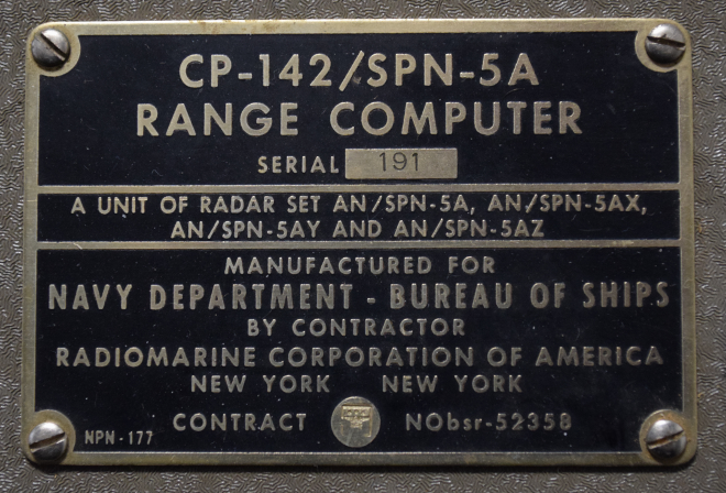
Cool. Thanks for posting, the descritpion of the knob is perfect. Although I think this is Korean-War era, not WWII. S/N 180 is available here, (https://www.worthpoint.com/worthopedia/vtg-navy-korean-war-era-tube-range-1849517762) and has a stamped manufacturer date of ’54. I am not an expert, but I think all SPN style RADAR are used in ATC, Navigation for landing assist etc., something that would not have been in common use in WWII. S=Surface ship P=Radar, N= Navigation (From : “100 years of RADAR”, G. Galati Springer press 2016). Great find.
I’d second that. The color-coded vinyl insulation wasn’t much of a thing in WW-II mil-spec stuff, which (IIRC) were heavy on woven insulation. By the point I had any direct experience with the innards of mil-spec stuff as a young engineer working for a defense contractor in the late 80’s, the specs had changed again favoring teflon-ey insulation that tended to be labelled with a stamping machine instead of color coded.
If they were retiring these things in 54, then it must have been installed in 1950 or late 40’s. So used in Korea definitely, but tech is tail end of WWII.
Definitely a blurry line between WWII and Korean era tech anyway. A lot of the stuff developed at the end of WWII came forward to Korea as it was only a few years later.
that’s a good observation, especially with the advances being made even late war, on near monthly basis. Our boat was built near the end of the war, but the entire radar system control was on a single stereotypical round CRT with only a few controls. Everything else was done manually on the chart table next to it, as space was a premium on a small vessel. Ive talked with vets who were radio and radar operators who speak a lot about still doing things “the old way”..which is what, the old old old way now?
I’d agree. Range and target computers from the second world war were mechanical as far as I’ve ever known.
There’s a great video series from the navy on youtube btw: https://www.youtube.com/watch?v=s1i-dnAH9Y4
Looks like it was a component in this radar system http://radar.tpub.com/TM-11-487C-1/TM-11-487C-11171.htm
Well, it says that much on the name plate…
that doc’s dated 1965. If it was for current spec at the time, this is well past WWII.
https://www.youtube.com/watch?v=s1i-dnAH9Y4
I’ve watched the description of the completely mechanical one several times. I love the 3D cam solution.
Whoops, not the same thing, but interesting none the less.
I’ve watched that whole series on mechanical fire control computers. It’s fascinating stuff.
I once bought a broken 8mm projector on ebay. It used the same technique to bundle the wires.
I prefer to braid wires if they are not too long, f.ex. inside computer cases from the buttons and LEDs to the mainboard.
Surface looks somewhat like Hammer paint treatment
https://en.wikipedia.org/wiki/Hammer_paint
That’s not hammer tone paint, hammer tone is usually done by adding silicone to the paint to get the separating effect.
That.s traditional WRINKLE paint like KENNEDY tool boxes had for decades or think modern Ferrari intake manifold paint.
From my understanding it was accomplished by by putting down oil based enamel and OLD SCHOOL lacquer memory is fuzzy on exact order but the difference in drying time between the 2 types of paint created the wrinkle effect.
This process has all but disappeared because OLD SCHOOL true lacquer paint is nasty volatile shit and enviro regs have stopped it’s use.
The effect can be achieved diy with modern enamel/lacquer paints but the finish can be quite variable because of atmospheric conditions.
Most of the big name spray paint companies offer a wrinkle coat in a couple of basic colors ie black, white, grey, but I found RILOPLAST is available in multiple colors and they will apparently do custom tints also, problem is they are in Italy so that can be a logistical issue for some of us.
No need to tear it down to make it into a USB controller! Just use an Arduino and a frequency counter to read the value of the pot and feed that into a computer.
Bonus points for interfacing with an Apple ][ running the Artillery game.
Scorched Earth!
A few of the switches I inherited from my father, an electrical engineer and ham radio operator, have that fiberboard sandwich style construction. I’ve never taken one apart (surprisingly) to see how it works inside.
I’ve seen it often too. It’s a more robust body construction than just bakelite.
The device you have isn’t listed in the components of the SPN-5 radar, so it must be a later addition.
Here’s my guess, based on the connectors and the complexity of the circuitry inside. “Computer” is probably a bit of a stretch. I suspect what this thing did, was to take a signal from the radar, allow you to modify it in some way by turning that “Miles” knob, and send something back to the radar system.
What’s most likely, would be a marker dot that was displayed on the radar display screen. As you turned the knob, the marker would move, and eventually line up with the dot on the display marking the target. You’d then read the range off the “Miles” dial. So it’s a “computer” in the sense that it allows you to “compute” the range of a target.
Just a guess, and some more aggressive Googling will probably provide the answer.
From Google: https://maritime.org/doc/ecat/index.htm
“Radar set AN/SPN-5 is a high resolution radar designed for navigational use aboard small Naval vessels. It is identical to Radiomarine Corp. of America model CR-101-A”
Anyone here actually know the name of that crinkly metal surface pattern on the device, and how it’s achieved? My off-the-head guess is beating with a rough hammer, but that would be hard to scale up to wartime production levels.
Either that, or some kind of spray coating, since it does bear some resemblance to a particularly bad coat of paint.
https://en.wikipedia.org/wiki/Hammer_paint
It’s commercially available in spray cans from Krylon and Rustoleum.
We use it all the time on equipment, it’s a cheap, decent-looking finish and the texture covers a lot of minor sins.
The Rustoleum stuff in particular sticks well to both steel and aluminum.
One downside – the stuff is lacquer based, so cleanup can be a bit of a pain if you get too enthusiastic.
Google “hammertone paint”
This is NOT hammertone tho. If you look closely, you see that its little wrinkles – like the surface of a coral.
That’s either due to age and chemical changes in the paint, or just the way the coated stuff back in the day to make it less slippery. Looks pretty dope to be honest.
True enough, it is wrinkle finish, not hammertone. It’s a similar product, though. It’s also available in a spray can from Rustoleum.
It goes on smooth and shiny and the wrinkles form as it dries. It’s kind of organic to watch.
Google “wrinkle paint” for a source.
I’ve used both hammertone and wrinkle paint on equipment in the past. In my experience they both produce a good finish, with the texture doing an incredible job of hiding all the little imperfections and scratches in the underlying surface, so it’s a great way to finish off metal enclosures without requiring an enormous amount of surface prep.
I also find the hammertone paints to be pretty darn hard and durable.
(There are also similar finishes available in powder coat products, btw, which also have the advantage of being kind to less-than-perfect surfaces)
I mad a more in-depth reply to another comment, check out http://www.gasup.it/en/riloplast/ they offer wrinkle paint in multiple colors and can apparently do custom tints also.
Another way is to get clear LACQUER spray paint and use regular enamel colors and by doing some testing you can get VERY GOOD results by spraying them on top of each other while still WET as the differences in drying times causes the wrinkles.
Keep in mind atmospheric conditions will heavily dictate how well it works because ot the effect on the lacquer dry time especially.
Connects to the RF out, “Welcome back Professor Falken, it’s been a while.”
It’s not hammertone finish…that has more of a dotted/heammered look. This is call crinkle finish, a paint that has an additive and or heat dried quickly to make it crinkle up and add the rough texture. I believe it was used to make the paint more durable and scratch resistant. A modern version : https://www.rustoleum.com/DigitalEncyclopedia/product-catalog/RustOleumUSA/consumer-brands/universal/consumer-brands/auto/specialty-paints/wrinkle-finish
Gorgeous :) Hope HaD has more vintage teardowns like this :)
I have been aware of old military hardware using wire lacing since high school when I had a chance to observe the final stages of an A-6 Texan war bird restoration being completed. I remember how neat and orderly the wiring in the open panels and bays looked. not only were the wires in neat bundles held by a flat “string” which the plane owner and others doing the restoration told me was called lacing, the lace had PRINTED letters and numbers on it which Identified what the wires connected and where those connections were, and this also matched the technical manuals for that aircraft! Sure beats “blue with white stripe”, type wire id’s found in todays cars cause gosh after 20 years its so easy to tell the former from “white with blue stripe” or “yellow with violet stripe” !!
When I put projects together from that day forward I used that level of neat precise work to be the goal for me to strive for, not that I ever even came close to it but it did keep my wiring from being described as rats nest or spaghetti ! (spaghetti is yet another old world wiring product, think shrink tubing without the “shrink” !! )
When I worked for a company that made wire harnesses for a variety of manufacturers. They had a machine that would hot ink stamp information right on each wire, either at the connectors or repeatedly along its length.
Not every manufacturers wanted to pay the extra expense to have that done.
That stacked construction is called a “leaf switch”, they turn up in surplus all the time: https://www.surplussales.com/switches/swleaf-1.html
Phone jacks are made the same way: https://www.allelectronics.com/item/swc-334p/1/4-phone-jack-leaf-switch-type/1.html
I found a picture …
http://armymunitions.tpub.com/mm50058/mm500580214.htm
As an old timer it is amusing to read a youngster’s appreciation of what to me is a bit of standard looking equipment for the time, but as others have said not WWII equipment. What seems strange if you haven’t seen it before is in fact absolutely normal construction methods and components, for the time. Also ‘computer’ is quite an old word and meant someone, or something, that computed. Around the time that equipment was constructed a computer could be human, analogue or digital.
I have just finished dusting off an old ohmmeter I bought it this weekend in a junk shop, it’s in a nice oiled wood case with a leather strap and is at least 50 years old. After re-soldering a couple of bad joints is works fine, old kit is great.
Oh yes, the fibre board is some form of paxolin, used to make tag strips and other insulating things. I have a raspberry pi case that uses the same construction technique (stacked cut-out shapes) as the switch, but acrylic sheet instead of paxolin.
Thanks for posting; the older radar equipment can be fascinating.
I’ve actually had experience driving a 50’s era military analog radar display for simulation. As many others have indicated, this was most likely used “compute” the analog range of the radar by changing the corresponding analog waveform.
While I haven’t interfaced with the specific device you acquired, the radar systems of this era that were used for simple broadcast and detection typically had three key signals:
1. Angle of RADAR dish. In a pre-digital era, this was typically captured using a synchro-resolver circuit
2. Analog signal which captures the timing of the RADAR signal traveling through space. The further the range setting of the RADAR, the longer each period of this waveform. This was typically captured with a triangle waveform.
3. Analog video signal which captured any return reflections.
For actually showing the image on the RADAR screen, the “home” or “default” position of the electron beam on the stroke RADAR display is in the center of the display. The triangle waveform from item 2 above mapped the distance traveled by the RADAR signal, including the travel time for the reflection to return to the source. In application, this triangle wave represents the position of the electron beam, starting from the center of the screen, following the angle described in the synchro-resolver circuit, towards the outside of the screen.
The system is aligned such that as the beam makes repeated scans starting from the center of the screen traveling outward, the intensity of the beam is defined by the video signal (item 3 above) as reflections are detected. Weak reflections result in weak video intensities (and weak illumination on the phosphor display) while strong reflections create a strong, or bright, response on the display. This entire process repeats quick rapidly and results in the classic sweeping scan.
Typically there is also a “blanking” period during which the video signal is blocked from receiving inputs between the end of one angular scan and the start of the next angular scan.
Based on your signal and labeling, I’m assuming your “computer” was used to define item 2 above: the timing of the analog components to synchronize the system (including the display) to the distance setting.
Just out of curiosity:
* Have you tried computing how far a signal would travel at any of the given dial settings, and seeing if there is a correlation to the period of the waveform?
* Does the waveform remain as a sine wave, or does it change shape?
If you’re interested in digging a bit further, it might be possible to further identify exactly how/where this particular component fit into its particular system.
Ma Bell liked to use sandwiched fiberboard on components, it’s possible that particular switch was made by Western Electric.
interestingly enough, a LOT the official Navy documentation on 40’s tech IS on the internet, thank whichever deity you choose. Without it I would be lost on most of the repair, teardown and maintenance projects I do on the USS LCS-102. their stuff on the Mk 14 Gyro Gunsight (we have two new in depot boxes, minus power supplies) has been a huge help. I go thru here to start, and if documents aren’t scanned, you can find which physical repository they’re in and can call for access there if needed. https://maritime.org/search.htm
Another fantastic piece of WWII equipment was the Odograph, the GPS of its day. It was a jeep-borne analog computer which incorporated distance travelled with a compass and outputted the course on an XY plotter.
Sort of like a sophisticated north-pointing chariot.
Have a look at this page, scroll down to “Odograph stuff”
http://jeepdraw.com/pauls.html
http://g503.com/forums/viewtopic.php?f=10&t=37990
http://jeepdraw.com/images/jeepdraw/pauls/ODOGRAPH-MECHANIX_ILLUSTRATED_1944-01.jpg
I forgot to mention these devices were built by IBM and another company.