I was splitting wood one day a few years back, getting next winter’s firewood ready on my hydraulic splitter. It normally handled my ash and oak with ease, but I had a particularly gnarly piece of birch queued up, and the splitter was struggling. The 20-ton cylinder slowed as the wedge jammed in the twisted grain, the engine started to bog down, then BANG! I jumped back as something gave way and the engine revved out of control; I figured a hydraulic hose gave out. Whatever it was, I was done for the day.
I later discovered that a coupler between the engine shaft and the hydraulic pump failed dramatically. It was an easy fix once I ordered the right part, and I’ve since learned to keep extras in stock. Couplings are useful things, and they’re the next up in our series on mechanisms.
Matching the Mismatched
Couplings like the one that failed on me have a few general uses. First and foremost, they do exactly what the name implies: they couple together two shafts to transmit rotational force. Most couplings transmit rotation between shafts that are more or less on the same axis, with some exceptions that we’ll cover below.
Depending on the needs of the design, couplings can either be rigid or flexible. Rigid couplings are for well-constrained systems where the two shafts are not likely to get out of perfect axial alignment. Rigid couplings include sleeve or muff couplings which generally clamp to the shafts with grub screws and which may have a keyway machined into the bore for better torque transmission.
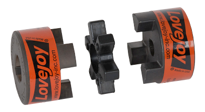
If there’s any chance of misalignment between shafts, though, a flexible coupling is called for. While not designed for transmitting torque through a wide angle, flexible couplings do allow shafts to get as much as a few degrees out of alignment without causing damage. This is important in devices where vibration or flexibility in the structure is likely to let the shafts move slightly relative to each other, like on my log splitter. In that case, the shafts were coupled by a jaw coupling, often known by the trade name Lovejoy. Lovejoy couplings have two metal halves with castellations that nest within each other. The metal is prevented from contacting directly by a tough elastomeric spider which both cushions rapid changes in torque and allows the shafts to flex a bit.
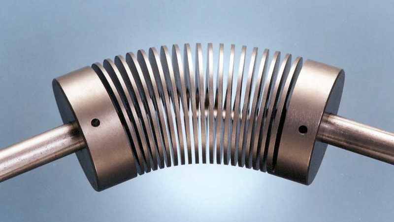
Another flexible coupling often seen in hardware projects is the beam coupling. Commonly found between stepper motors and lead screws in larger CNC machines, beam couplings look a little like stocky springs that have been machined out of a single cylinder of material. The springiness allows for a little angular flexibility and even for some end play which could allow the shafts to get closer or farther apart. Beam couplings are typically machined from aluminum, but other metals and even polymers are used too.
Joints: Universal and Constant
When misalignment between shafts is more than a couple of degrees, or when a lot of torque needs to be transmitted through a wide range of angles, different kinds of couplings are called for. The canonical coupling in this category would probably be the universal joint, commonly used in automotive driveshafts. The familiar design of nested yokes joined by a cross or spider dates back far into history, with early examples showing up on Greek siege engines. The great English scientist Robert Hooke would later study these devices and characterize them mathematically. He realized that the output rotation was not necessarily constant at every angle and worked out how to fix this: a pair of joints at each end of a shaft rotated 90° axially. This arrangement can still be seen on conventional driveshafts for rear-wheel-drive vehicles, with a U-joint at the output of the transmission and another at the differential input.
For shorter shafts, like on the drive axles of front-wheel-drive vehicles, there may not be room for a pair of U-joints. To accommodate this, another flexible coupling is used: constant velocity (CV) joints. CV joints look a little like beefy ball bearings with concentric races with deep, wide grooves. Large steel balls ride in each groove and transmit torque between the inner and outer races. CV joints can work through a large angular range and are usually used in pairs on each axle.
There is a wide range of other couplings that we haven’t touched on here, from flexible couplings that use metallic bellows or even fabric or polymer diaphragms to couplings like torque converters and magnetic couplings that allow for rotational slippage. For almost every application requiring torque to be transmitted between shafts, there’s a coupling that’s right for the job.


Were you the one with the chainsaw/kevlar incident written up a while back?
+1
No that was the lumberjill
Viscous coupling. Not to be confused with a torque converter.
https://en.wikipedia.org/wiki/Viscous_coupling_unit
There’s even using a electrorheological fluid as part of some.
GM (Chevy?) used a “non-Newtonian” silicone fluid in transfer cases in the early 1990’s.
Shear, (discontinuity between the front and rear axle rotation) caused the fluid to stiffen, thereby coupling the (normally) non-driven axle to the power train.
They now use it in their “mag ride” shock absorbers for adjustable damping
Subaru justy and land rover Freelander 1 used this system too. fwd, with a viscous coupling to the rear.
All manual non-STi subarus hafe a viscous center diff. When all is fine, it acts like a regular open diff, but when the rotational speeds of front and rear start to differ too much, the viscous coupling can almost lock the diff completely.
Justy used a vacuum actuator to engage the rear drive, at least in the US
Volkswagen used something like this in the AWD Vanagon in the early ’80s. My ’69 microbus was much cooler than the Vanagon though… :-)
Volkswagen used to use those for the old and rare “Syncro” badged AWD models.
The beam coupling is similar (same as?) the spring on the starter motor of my old Ford. It absorbs the shock of the rotating starter gear as it engages the flywheel.
Here’s a photo.
http://www.vanpeltsalesstore.com/New-Starter-with-Ford-type-drive–6-Volt_p_637.html
Here is another coupling which is very interesting – the axes must be parallel, but can have a (fairly large) offset.
https://www.youtube.com/watch?v=_iIsibuIs08
I learned something new today! (TM)
You are not allowed to reveal sorcery to mere mortals, you will be punished!
I found this in a copy of Mechanisms and Mechanical Devices Sourcebook (It’s on the cover of my edition….)….I built one using three “Y”-shaped pieces instead of discs. The two axles can be slightly out of parallel, depending on the looseness of the connections on the ends of the six connecting rods. Also, you do NOT want the two end axles to come in line with each other, or that center section will start swirling around in a VERY unbalanced fashion
Very similar to the Oldham coupling, which might be a little simpler and cheaper but would have more friction:
https://www.youtube.com/watch?v=2ibsOu_TrZc
Ah, the old Lovejoy coupling brings back memories as we used them on our rotary van vacuum pumps in the machine shop. Whenever the motor or pump were removed for servicing, you had to take great care in aligning the two shafts as that coupling did not like non-alignment at all. Ask me how I know, ha ha. If you were lucky, it just chewed up that rubber insert…if you were not lucky, one or more of those metal ears would let go creating a bit of a racket…and some shrapnel.
Thank you for the “Learn Engineering” video.
That channel has great animations. Subscribed.
my favorite
https://upload.wikimedia.org/wikipedia/commons/thumb/0/0f/TireClutch.JPG/538px-TireClutch.JPG
+1
That looks like something I would come up with.
I never knew the brand name, I’ve always just referred to them as “spider couplings”.
Right now I have one on the Z axis of my main 3D printer, I like it because it’s a rigid coupler but with a slight amount of give. Plus I can lift the gantry straight off the stepper for maintenance which is awesome.
It’s apparently called a “Lovejoy coupling”
https://www.google.com.au/search?q=Lovejoy+coupling&source=lnms&tbm=isch&sa=X&ved=0ahUKEwiqqrSnu6TaAhVHvLwKHTeTCewQ_AUICigB&biw=1280&bih=931
If you search for “spider coupling” you get images of exactly the same mechanism, just unbranded.
Well, it says that much in the article…
I worked at a company in the ’80s that had a product that used a 2 cylinder Briggs and Straton engine that drove a roots style blower. It worked great and had done so for years. One of our customers wanted a smaller version, so we built one with a smaller one cylinder motor and a smaller blower. It didn’t work so well. With half the power strokes on the engine and a smaller blower, a resonance occurred that would destroy every coupling that was used between the units. Some threw shrapnel violently across the lab, the ones with rubber lasted a bit longer, but eventually, the rubber got so hot that it failed. Sometimes it shot rubber balls out of the coupling shortly before total failure. The resonance was obvious, but the ME working on it and the GM of the company just kept trying new couplers. I suggested machining a flywheel to go on the blower side of the coupling to try and change the frequency that the resonance became serious at. I had two strikes against me. I was a student, and I was majoring in EE, so the ME blew me off. I still think it would have been worth a try, it would be easy and wouldn’t have left us worse off if it didn’t work. I left the company a year later, and the prototype was sitting in the corner of the lab collecting dust.
I have seen a video where somebody coupled an automotive alternator to a one cylinder (B&S ?) engine. The spidercoupling crapped out in similar fashion. The guy mentioned, that he found out this things do really not like torque pulsations. He switched to a belt drive (what he wanted to avoid at the beginning.
So perhaps it was not just resonance, but the pulsation altogether. Then your flywheel at the blower side could have worsened the problem and an extra flywheel at the engine side could have been a solution.
That makes sense. It’s a shame that the ME didn’t think of either one…
modern automotive dual mass flywheel would have likely solved this as one of the design considerations is the immense hammering a gearbox gets by a modern diesel thumping away at full throttle and low rpm the dual mass flywheels help keep the gearbox in one peace
I always wondered how it’s physically possible to assemble two yokes and a cross to make a universal joint. Can someone smarter than me explain the process? The geometry of assembly seems impossible.
First idea: make the cross with holes and insert the pins at assembly time with a hammer or press.
Other possibility: Make the yokes with enough distance to insert the cross and use a big press to close it.
The holes in the yokes are oversized and contain a (plain) bearing. The cross is inserted into the first yoke from the inside, then the bearings get pressed in or mounted from the outside. Then the other yoke is positioned “around” the cross and it’s bearings inserted. Since the bearings don’t have to hold much of an axial force (in the bearing axis that is) they can be held in place by a simple press fit or using something like cir-clips or a retainer ring. As long as they stay in place under the centrifugal forces anything’ll do.
the bearings in automotive yolks are usually needle roller, but assembly is the same indeed there are likely many YouTube videos of the process.
Clever idea here for low torque applications. On the project site a plastic tube and zip ties are shown in the vid for coupling.
https://hackaday.com/2013/01/21/award-clock-put-to-good-use-as-a-bench-meter/#more-93328
These couplings are about a lot more than shaft misalignment. They also prevent certain vibration and shock loads between the engine and hydraulic pumps from being transferred between the two.
If you need a simple limited range Axis-Agile Drive Coupling, use a Phillips-Head screwdriver bit into a Phillips-Head screw or bolt mounted in a chuck of some sort. It’s not ideal, but it is very simple and with careful design, it is (within limits) robust.