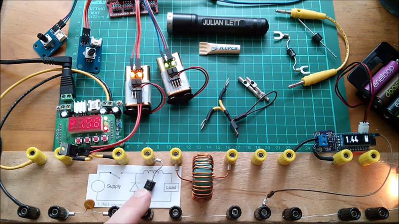
We always appreciate when someone takes the time to build something and then demonstrates what different design choices impact using the real hardware. Sure, you can work out the math and do simulations, but there’s something about having real hardware that makes it tangible. [Julian Ilett] recently posted two videos that fit this description. He built a buck converter and made measurements about its efficiency using different configurations.
The test setup is simple. He monitors the drive PWM with a scope and has power meters on the input and output. That makes it easy to measure the efficiency since it is just the ratio of the power output to input. You can see the two videos, below.
It is interesting to see that the various design options do change the efficiency, but perhaps not by as much as you would think. The range wound up being 72% to 84% — unless you count removing the low-side device which led to 0% efficiency because the circuit won’t work without it.
If you want a refresher on how a buck converter — that is, a DC to DC converter that reduces a higher input voltage to the desired voltage — works we had a good brief video about that recently. If you want a little more whiteboarding and explanation, you might enjoy the Sparkfun video on the same topic.


Did he try a synchronous rectifier? That is, using two transistors (one from Vin, one from ground) to supply the input to the inductor? I think that’s a thing a lot of modern controllers use to improve efficiency.
Oh never mind. 2nd video.
Good start for further investigation into the losses. RDSon too high? Gate capacitance? Inductor losses?
It shouldn’t be that hard to hit 90%.
+ im sure super long leads between components dont help
If you are going to have wires all over the place in a switching regulator at least use a current probe to determine where the electrons are being wasted.
Sync. Rects work better than shottkys depending on certain factors like output current and output voltage. You can always buy a lower rdson fet and have more choices to do so than with a shottky.
There is a video on Youtube of a English dude try to rip into a high voltage buck convert module from China. Now I am not saying there are not any fake parts coming out of China (re: FTDI gate). But it’s totally laughable how he goes about it. He throws on a Car signal lamp bulb, on the output and proceeds to apply high voltage to the input of the converter. He even says it in the video, “He has no idea what the values are for the bulb. It’s his goto supply load.” I have used signal bulbs for loads before. But I measured the load. It’s not uncommon to find 12V @ 2 amps.
He has no clue why there is smoke coming off the converter. He just relates it to a fake parts. As this article here is talking about efficiency in power supplies. If the English dude had a clue, he would realize his buck convert is dissipating over 5 watts. Sorry but none of those parts on a Chinese buck converter even 100% real could handle it. Hence all the magic coming out of the parts.
I watched a couple of his videos in the past when he was playing with cheap power banks and I was quite disappointed to see how pointless the experiments were. Similar feeling here, I guess the idea of removing the diode in the buck says a lot about his understanding of the buck converter. I hope one day someone will be able to turn Mohan’s book into Youtube material and still keep people’s attention for 30 minutes-a-video.
When you use MOSFETs as rectifier, you are not supposed to simply use the internal body diode. There are several MOSFET rectifier schematics, which can be use to cause MOSFET to rectify by actually switching itself depending on polarity. Some of these schematics are more efficient than others, but it all boils down to how high is gate voltage.
When you write Harvie.CZ “not supposed to” are there any particular technical reasons you observe which limit utility from say the lowest end products, where almost anything will do, towards peculiar specifications eg noise characteristics for higher end products ?
Reason I ask is many years ago when this subject came up it turned out the MOSFETs of that era were reducing on the cost curve more responsively to market dynamics whilst rectifier diodes nowhere near as much, the differential in terms of demand then offered slight advantages for higher end products to go with MOSFETs instead of classic diodes and packaging issues as well. In other words the notion of “not supposed to” was more a short term commercial one (pushed by wholesale vendors to a degree) regarding demand/cost logistics in a dynamic rather than anything purely technical…
I’m not saying you should not use MOSFETs as rectifiers. I am just saying there are better ways of using the exact same MOSFET as more efficient rectifier with less power loss. That is when you use the actual MOSFET switching capability instead of its internal diode. No BOM change there.