
We got a question from [DC Darsen], who apparently has a broken electronic organ from the mid-70s that needs a new top-octave generator. A top-octave generator is essentially an IC with twelve or thirteen logic counters or dividers on-board that produces an octave’s worth of notes for the cheesy organ in question, and then a string of divide-by-two logic counters divide these down to cover the rest of the keyboard. With the sound board making every pitch all the time, the keyboard is just a simple set of switches that let the sound through or not. Easy-peasy, as long as you have a working TOG.
I bravely, and/or naïvely, said that I could whip one up on an AVR-based Arduino, tried, and failed. The timing requirements were just too tight for the obvious approach, so I turned it over to the Hackaday community because I had this nagging feeling that surely someone could rise to the challenge.
The community delivered! Or, particularly, [Ag Primatic]. With a clever approach to the problem, some assembly language programming, and an optional Arduino crystalectomy, [AP]’s solution is rock-solid and glitch-free, and you could build one right now if you wanted to. We expect a proliferation of cheesy synth sounds will result. This is some tight code. Hat tip!
Squeezing Cycles Out of a Microcontroller
Let’s take a look at [AP]’s code. The approach that [AP] used is tremendously useful whenever you have a microcontroller that has to do many things at once, on a rigid schedule, and there’s not enough CPU time between the smallest time increments to do much. Maybe you’d like to control twelve servo motors with no glitching? Or drive many LEDs with binary code modulation instead of primitive pulse-width modulation? Then you’re going to want to read on.
There are two additional tricks that [AP] uses: one to fake cycles with a non-integer number of counts, and one to make the AVR’s ISR timing absolutely jitter-free. Finally, [Ag] ended up writing everything in AVR assembly language to make the timing work out, but was nice enough to also include a C listing. So if you’d like to get your feet wet with assembly, this is a good start.
In short, if you’re doing anything with hard timing requirements on limited microcontroller resources, especially an AVR, read on!
Taking Time to Think
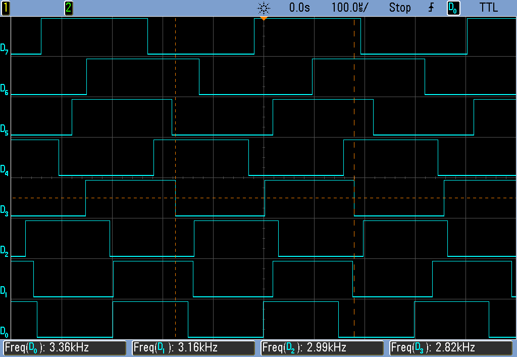
The goal of the top-octave generator is to take an input clock and divide it down into twelve simultaneous sub-clocks that all run independently of each other. Just to be clear, this means updating between zero and twelve GPIO pins at a frequency of 1 MHz or so — updating every twenty clock cycles at the AVR’s maximum CPU speed. If you thought you could loop through twelve counters and decide which pins to flip in twenty cycles, you’d be mistaken.
But recognizing the problem is the first step to solving it. Although the tightest schedule might require flipping one pin exactly twenty clocks after flipping another, most of the time there are more cycles between pin updates — hundreds up to a few thousand. So the solution is to recognize when there is time to think, and use this time to pre-calculate a buffer full of next states.
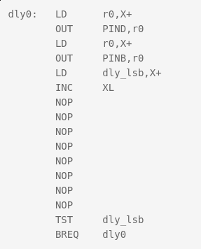 [Ag]’s solution uses a few different loops that run exactly 20, 40, and 60 cycles each — the longer versions being just the 20-cycle one padded out with
 NOPs. These loops run inside an interrupt-service routine (ISR). When there are 80 or more cycles of thinking time until the next scheduled pin change, control is returned to the main loop and the next interrupt is set to re-enter the tight loops at the next necessary update time.
All the fast loop has to do is read two bytes, write them out to the GPIO pins, increment the pointer to the next row of data, and figure out if it needs to stall for 20 or 40 additional cycles, or set the ISR timer for longer delays and return to calculations. And this it can do in just twelve of the twenty cycles! Slick.
Buffers
Taking a step back from the particulars of the top-octave generator, this is a classic problem and a classic solution. It’s worth your time to internalize it, because you’ll run into this situation any time you have real-time constraints. The problem is that on average there’s more than enough time to complete the calculations, but that in the worst cases it’s impossible. So you split the problem in two parts: one that runs as fast as possible, and one that does the calculations that the fast section will need. And connecting together fast and slow processes is exactly why computer science gave us the buffer.
In [AP]’s code, this buffer is a table where each entry has two bytes for the state of the twelve GPIO pins, and one byte to store the number of clock cycles to delay until the next update. One other byte is left empty, yielding 64 entries or 256 bytes for the whole table. Why 256 bytes? Because the AVR has an 8-bit unsigned integer, wrapping around from the end of the table back to the beginning is automatic, saving a few cycles of wasteful if statements.
But even with this fast/slow division of labor, there is not much time left over for doing the pre-calculation. Sounding the highest C on a piano keyboard (4186 Hz) with a 20 MHz CPU clock requires toggling a GPIO pin every 2,390 cycles, so that’s the most time that the CPU will ever see. When the virtual oscillators are out of phase, this can be a lot shorter. By running the AVR at its full 20 MHz, and coding everything in assembly, [AP] can run the calculations fast enough to support twelve oscillators. At 16 MHz, there’s only time for ten, so every small optimization counts.
Some Optimization Required
Perhaps one of the cleverest optimizations that [AP] made is the one that makes this possible at all. The original top-octave chips divide down a 2 MHz square wave by a set of carefully chosen integer divisors. Running the AVR equivalent at 2 MHz resolution would mean just ten clocks per update and [AP]’s fast routine needed twelve, so the update rate would have to be halved. But that means that some odd divisors on the original IC would end up non-integral in the AVR code. For example, the highest C is reproduced in silicon as 2 MHz / 239, so to pull this off at 1 MHz requires counting up to 119.5 on an integer CPU. How to cope?
You could imagine counting to 119 half of the time, and 120 the other. Nobody will notice the tiny difference in duty cycle, and the pitch will still be spot on. The C programmer in me would want to code something like this:
uint8_t counter[12] = { 0, ... };
uint8_t counter_top[12] = { 119, ... };
uint8_t is_counter_fractional[12] = { 1, 0, ... };
uint8_t is_low_this_time[12] = { 0, ... };

// and then loop
for ( i=0 ; i<12; ++i){
  if ( counter[i] == 0 ){
    if ( is_counter_fractional[i] ){
      if ( is_low_this_time[i] ){
        counter[i] = counter_top[i];
    is_low_this_time = 0;
      else {
        counter[i] = counter_top[i] + 1;
    is_low_this_time = 1;
      }
    }
  }
}
That will work, but the ifs costs evaluation time. Instead, [AP] did the equivalent of this:
uint8_t counter[12] = { 0, ... };
uint8_t counter_top[12] = { 119, ... };
uint8_t phase[12] = { 1, 0, ... };

for ( i=0 ; i<12; ++i){
  if ( counter[i] == 0 ){
    counter[i] = counter_top[i] + phase[i];
    counter_top[i] = counter[i];
    phase[i] = -phase[i];
  }
}
What’s particularly clever about this construction is that it doesn’t need to distinguish between the integer and non-integer delays in code. Alternately adding and subtracting one from the non-integer values gets us around the “half” problem, while setting the phase variable to 0 means that the integer-valued divisors run unmodified, with no ifs.
The final optimization shows just how far [AP] went to make this AVR top-octave generator work like the real IC. When setting the timer to re-enter the fast loop in the ISR, there’s the possibility for one cycle’s worth of jitter. Because AVR instructions run in either one or two clock cycles, it’s possible that a two-cycle instruction could be running when the ISR timer comes due. Depending on luck, then, the interrupt will run four or five clocks later: see the section “Interrupt Response Time” in the AVR data sheet for details.
In a prologue to the ISR, [AP]’s code double-checks the hardware timer to see if it has entered on a one-cycle instruction, and adds in an extra NOP to compensate. This makes the resulting oscillator nearly jitter free, pushing out a possible source of 50 ns (one cycle at 20 MHz) slop. I don’t think you’d be able to hear this jitter, but the result surely looks pretty on the oscilloscope, and this might be a useful trick to know if you’re ever doing ultra-precise timing with ISRs.
The Proof of the Pudding
Naturally, I had to test out this code on real hardware. The first step was to pull a random Arduino-clone out of the closet and flash it in. Because “Arduinos” run at 16 MHz with the stock crystal, the result is that a nominal 440 Hz concert A plays more like a slightly sharp F, a musical third down. It sounds fine on its own, but you won’t be able to play along with any other instruments that are tuned to 440 Hz.
[AP]’s preferred solution is to run the AVR chip at 20 MHz. Since the hardware requirements are very modest, you could use a $0.50 ATTiny816 coupled with a 20 MHz crystal and you’d have a top-octave generator for literal pocket change — certainly cheaper than buying even an Arduino clone. I tested it out with an ATMega48P and a 20 MHz crystal on a breadboard because it’s what I had. Or you could perform crystalectomy on your Arduino to get it running at full speed.
We went back and forth via e-mail about all the other (firmware) options. [AP] had tried them all. You could trim the ISR down to 16 cycles and run at 16 MHz, but then there’s only enough CPU time in the main loop to support ten notes, two shy of a full octave. You could try other update rates than 1 MHz, but the divisors end up being pretty wonky. To quote [AP] from our e-mail discussion on the topic:
“After playing with the divider values from the original top octave generator IC and trying different base frequencies, it appears that the 2 MHz update rate is a “sweet spot” for getting reasonable integer divisors with < +/-2 cents of error. The original designers of the chip must have done the same calculations.”
To make a full organ out of this setup, you’ll also need twelve binary counter chips to divide down each note to fill up the lower registers of the keyboard, but these are easy to design with and cost only a few tens of cents apiece. All in all, thanks to [AP]’s extremely clever coding, you can build a fully-polyphonic noisemaker that spits out 96 simultaneous pitches, all in tune, for under $10. That’s pretty amazing.
And of course, I’ve already built a small device based on this code, but that’s a topic for another post. To be continued.


The artwork is great, as it usually is. But… can anyone explain to me what is going on there? Did Howard the Duck play an electric organ? Is there some cultural reference there that I am ignorant about? Help me, I am curious!
Thanks!
Pretty sure that’s a Donald the Duck costume, I’m none the wiser on any references though.
Elton John
See this Google image search…
https://www.google.com/search?q=elton+john+donald+duck&num=100&tbm=isch
That’s Elton John, playing a Hammond B3 organ. No top octave dividers or cheesiness in THAT organ!
The illustration is great, as usual. But.. What is going on there?
Was Howard the Duck into playing electric organs?
Is this some other cultural reference that I am ignorant of, maybe a perfomer who dresses/dressed up as a duck?
Help me, I’m curious!
Thanks!
https://www.youtube.com/watch?v=ynWhozyOoZQ
No, no, no… this is the right one
https://youtu.be/sjPrhUFXj4I
Google “Elton John duck suit”
That’s pretty bizarre.
Yep. Even for Elton…
Why not use a Teensy 3.2? 120 mhz clock.
Or a Cortex A8?
Some (many) faster CPUs have an instruction cache (and cache misses can ruin your day), and/or interrupt latency can be problematically huge.
Starting with a 20MHz CPU where every instruction takes guaranteed fixed time is sometimes an easier solution.
I was being ironic.
What does it take for something to not be cheesy for you Elliot? ;)
Anyways, my Polytron DCO runs 37 oscillators fully polyphonic.
With Envelope.
http://blog.dspsynth.eu/infinity37-a-fully-polyphonic-diy-synth/
https://youtu.be/WVLaLTqu8E8
I seem to recall that 2MHz was slightly under the desired frequency. Don Lancaster certainly covered this in one of his articles about electronic music in the seventies, probably in both his TTL and CMOS Cookbooks.
I did build programmable divider to play with thIs, using an ft-243 crystal. But then top octave generators arrived, and no need to build the equivalent.
Michael
Hi Michael,
I played around with different base clock frequencies, and 2 MHz seemed to work best in terms of pitch accuracy:
Note Divider Actual Freq Ideal Freq Offset
Hz Hz cents
C8 239 8368.2 8372.0 -0.8
B7 253 7905.1 7902.1 0.7
A#7 268 7462.7 7458.6 0.9
A7 284 7042.3 7040.0 0.6
G#7 301 6644.5 6644.9 -0.1
G7 319 6269.6 6271.9 -0.6
F#7 338 5917.2 5919.9 -0.8
F7 358 5586.6 5587.7 -0.3
E7 379 5277.0 5274.0 1
D#7 402 4975.1 4978.0 -1
D7 426 4694.8 4698.6 -1.4
C#7 451 4434.6 4434.9 -0.1
Worst case error was +/- 1 cent.
If you have a better base clock frequency, I’d love to try it.
Ag Primatic
The highest µC clock the lowest the error. The cheap blue pill can run at 72Mhz the error should be reduced by a factor of ~6.
I mean a facor of ~4
You have a great memory, Michael! I searched through the back issues of Popular Electronics, and found the articles by Don Lancaster from 1974(!) that you may have been referring to.
This article describes the equal tempered scale and the first mention of 8-bit and 9-bit divider values (called Series A and Series B in Table II in the article):
https://www.americanradiohistory.com/Archive-Poptronics/70s/1974/Poptronics-1974-01.pdf
page 39
This article describes building a tone generator with a 1.94204 MHz clock, which I’m assuming is the “under 2MHz clock” you were recalling:
https://www.americanradiohistory.com/Archive-Poptronics/70s/1974/Poptronics-1974-03.pdf
page 50
If you divide the 1.94204 MHz clock by 2, the ratios fit into 8 bits. The downside is that the pitch accuracy is +2.5/-2.8 cents, not as good as the 2 MHz version accuracy of +1/-1.4 cents, but probably still acceptable.
Also, I’m not sure where to source the 1.94204 MHz crystal (or its multiples) from. It doesn’t seem to be a standard value.
Ag Primatic
P.S. Don has an error in one of his 8-bit divider values. The value for F7 should be 174, not 176. Using 176, the pitch error would be -22 cents! Maybe I’ll send a correction to Popular Electronics….
Exceptional Hack! I tried for a while to do this without an ISR using a similar jump table between nearly-identical portions of code. However, this is a MUCH cleaner solution that doesn’t take a bunch of hard-coded unrolled loops. Eventually I ran out of time and wrote this off. However, it’s incredibly refreshing to see that someone else had a better approach that I could learn from. Kudos!
One minor optimization that you can do (if you’re so inclined) is that you can use 2 of the 8-bit hardware PWMs in the processor to generate 2 of the odd divider clocks (/239 and /253 are ideal since they fit in a single byte). From the summary in the article this means that you’re down to creating the 10 remaining pins via your software methods. That means you can get the same perfectly stable results with the stock 16MHz oscillator and no hardware changes to get all 12 signals (2 via PWM and 10 via software).
Great Job! I’m also glad I wasn’t the only one to lose some sleep over this as well!
I also tried initially to do this without an ISR. It was a painful exercise in clock cycle counting and trying to balance all paths through the code to be equal. The ISR made it so much cleaner, and it only costs a few extra clock cycles to enter and exit.
I may be inclined to take you up on your optimization so we can all use a stock 16 MHz Arduino. Great idea!
Ag Primatic
So I coded up your optimization of running 2 of the outputs directly from the unused timers and the other 10 via software, and it worked! With a 16 MHz clock, I can get all 12 outputs now.
Thanks for your suggestion, EMControl!
Ag Primatic
On a Propeller, generating 12 symmetrical clocks would be a matter of starting 6 cogs and letting each cog starting both of its Numerically Controlled Oscillators with different parameters. Once the clocks are running, it won’t even need to execute any code anymore. Just saying.
===Jac
Same dumb solution as a Teensy 3.6
Solder a couple of propellers in your 70-ties keyboard.
I think a $0.50 ATTINY816 with a 20 MHz crystal is the lowest cost solution for a top octave generator. All the other suggestions seem to be much higher in cost.
Mentioned so far:
Teensy 3.2 $19.80
Teensy 3.6 $29.25
Propeller $4.47
Plus, the ATTINY816 is available in a 20-pin SOIC package (tiny, but still hand-solderable), and it’s 5V compatible.
Slightly disingenuous. You’re comparing the price of discrete components (without the PCB that will be needed) with that of development boards. How much does a low-end ARM chip (from Microchip, Atmel, or STM, for example) cost? I can understand if you don’t want to bother with the research, but then don’t quote apples-and-oranges prices.
Propeller is a $4.47 IC in 10K quantities, not a board. So that’s an apples to apples comparison.
Teensy 3.2 uses a MK20DX256VLH7 processor that’s $4.85 in 10K quantities.
Teensy 3.6 uses a MK66FX1M0 processor that is $10.59 in 10K quantities.
You are welcome to provide data on your suggestions. Your target is $0.50.
I didn’t say that there was a cheaper solution, and I doubt that there is. I was only contesting your 40:1 to 60:1 ratio between an ATtiny16 and an ARM.
How about a PIC? https://www.microchipdirect.com/product/PIC16F15344
5V, 20 pin, 10 HW PWMs, 32MHz internal oscillator (no need for xtal if you don’t mind some drift). bit over your target $0.50, it’s at $0.63@5K. if you don’t need the whole 20 pins, they have $0.50@5K 14 pin controllers.
Here’s what I see as a problem with the PIC16 architecture in this application. Even though the PIC clock can run up to 32 MHz, the minimum instruction cycle time is 125ns. This is equivalent to an 8 MHz AVR processor. I doubt that this algorithm will function with only 8 instructions in the inner loop, even before trying to code it in PIC assembly.
That PIC would be perfect. After initialization, zero code overhead.
Ag Primatic – Those peripherals can be setup to take an external input pin and divide it down by a user selectable scaler with a user selectable offset. So it doesn’t matter if your main system clock is operating at 32kHz.
I would love a hackaday highlight or competition where projects use microcontroller peripherals instead of throwing clock cycles at problems.
10 HW PWMs is very close to 12, but I’m sure that some people would miss the remaining two notes per octave… Are you suggesting implementing the other two in firmware? Have done it it?
Price isn’t super-critical here, but Ag’s solution is definitely cheap and cheerful.
Hmm. From the data sheet, here’s the list of timing-related digital peripherals for the PIC16F15344:
• Complementary Waveform Generator (CWG)
• Two Capture/Compare/PWM (CCP) module
• Four 10-Bit PWMs
• Numerically Controlled Oscillator (NCO)
From which set of peripherals would you get the 12 divided-down frequency outputs with zero code overhead?
Equal Tempered is not is in tune with it self. Other temperaments should be easier to compute in fewer steps. The irrational number difference of ET tuning is a mess. If you are going this far you should have several temperaments available just like most modern keyboards and organs. Then there is Arabic tuning etc.
If this temperament thing is puzzling look it up and hear the difference. Scala.org has something like 3000 tuning scales of the whole musical world.
This is an issue with all synthesizers that derive their pitches from a single oscillator. The bottom line is, the higher the frequency you’re deriving the pitches from, the closer to the irrational ideal you can get.
Congratulations. I remember turning this over in my head a bunch and could not figure out a good solution… really neat work finding the “gaps” where there was enough time to compute more entries for the buffer.
I came across this when looking for Arduino information. I bought some pro minis (16MHz ATmega328P) for a project, want to program in assembler, looking through random articles. This seemed like a really good challenge, I have figured on paper a solution that I think will output all 12 notes with more accurate frequencies than the solution here. The only compromise I have made is that where transitions are closer than 2 microseconds they occur at the same time. Is it worth my time to continue – does anyone care? I am a bit of an assembler junkie, last efforts writing stuff for PIC16F628A a few years back. But new to Arduino so a minimal hardware project would be good learning before tackling my own project which is a bit more hardware dependent.
Hi Alan,
If you’re willing to summarize your algorithm, I’d be happy to see whether it would work for his application.
It would be okay if the duty cycles varied, but the periods of eiach note need to be unchanging for the tones to not warble.
Ag
I have written the program in Atmel Studio 7 and run it in the simulator and it appears to work.
Technique – a ring buffer 256 bytes with 4 byte cells: 2 byte timer, 2 byte port bits. Timer 1 is set to run from 0 to ICR1 and reset (ICR1 = 0x7FFF). For each cell a timer value is put into OCR1A, when Timer 1 hits that value the interrupt routine outputs the port bits then moves to the next cell and sets up a new value in OCR1A. That takes 18 clock cycles and there is some overhead in servicing interrupts so I allow 32 cycles (that’s where the 2 microseconds comes in). If a bit needs fiddling up to 32 cycles after the time in the cell, the bit is added to the port bits rather than getting a new cell.
The mainline has to load up the ring, it keeps the next times to flip bits in registers 0-23 (12 pairs=12 notes). When a cell becomes empty the 12 pairs are scanned to find the lowest value (takes about 80 cycles) and this is the selected time for the next cell. The subsequent flip time is then calculated for that note by adding the appropriate cycles (e.g. C8 4186.009 Hz has a flip period of 1911.128 cycles at 16MHz. For each note a 1 byte frac value is held in memory and concatenated with the register pair when updating so the note value is good to about 2 parts in a million.
As far as I can work out, the mainline spends about 140 cycles setting up each cell and the interrupt that services it takes maybe 30 = 170 cycles. There are on average over 200 cycles available so should be fine.
Is there a way to post the assembler source?
OK I loaded the program into a Pro Mini board (which is what I bought) using avrdude and it is definitely outputting some notes on some pins. I don’t have the equipment to say if they are the right notes and all presented on connections on the edge of the board (still climbing that learning curve). If someone wants to see if it is any good, just let me know where to send the source code.
Version 2 now seems to be working. Frequency of notes as before – accurate to 2ppm. Jitter now +-5 cycles or about +-350nS. Anybody got equipment to test it properly?
OK, here’s a quick back-of-the-envelope analysis.
Let’s take A7 as an example. The nominal frequency of A7 is 7040 Hz. This note would have a nominal period of 142.045 us. You are stating that you have +/- 350 ns of jitter, so that would make the period vary between 141.695 us and 142.395 us, or the frequency will vary between 7023 Hz and 7057 Hz. In cents (1/1200 of an octave), this would be a deviation of +/-4.17 cents.
According to Wikipedia (https://en.wikipedia.org/wiki/Cent_(music)#Sound_files), the Just Noticeable Difference (JND) for pitch is 5 to 6 cents, so a variation of more than 8 cents will be noticeable. In addition, there will be a time-varying beating between two simultaneously played notes that will also be audible.
My solution has the same accuracy as the original Top Octave Tone Generator (which is -1.4/+1 cents) and the tones have 0 cycle jitter, so the frequencies are as stable as the crystal oscillator (and no time-varying beating of two simultaneous notes).
I was also able to get all 12 notes generated from a standard 16 MHz Arduino by taking EMControl’s suggestion of having two of the notes generated by hardware timers, and the other 10 by the software algorithm.
I see a fundamental flaw in my thinking. I have produced a ‘top but one’ octave generator – . Which is a pity because it’s a good one. I assumed (bad thing to do) that we were talking about a piano, which has a top note of C^7. I’ll just have to double the clock frequency (or use two chips – now there’s a thought). The notes I produce are pitch perfect (give or take 2 parts per million). The A7 generated by a 2MHz clock is off by 28 ppm. The actual note periods are irrational so a digital source can only approximate the correct transition time, ideally to the nearest clock cycle. A 2MHz clock would be up to -+250nS out even ideally. I used the 16MHz clock and as long as producing a single note it will be as good as the variation in latency of the interrupt routine (0,+1 cycle – I don’t use any three cycle instructions in the mainline). The problem comes when transitions are required for two or more notes close together. In that case some transitions are moved +- up to 4 cycles. Which is what I called jitter. Since it occurs about 1 transition in 5 it would be inaudible. Back to the drawing board. I thought it was too easy.
Most likely, you already have the best test equipment for this – the mark I biological auditory sensor. It’s nice for the frequencies to be right, especially if you’re going to play with other instruments, but the only adequate test of whether +/- 5 cycles is good enough is by listening to it.
Furthermore, the percentage error (or parts per million) doesn’t mean a thing – what’s important is how many Hertz the pitches are off, particularly each note compared with the others. There’s nothing more annoying than playing a chord and hearing a 5-10 Hz “flutter”. This flutter is caused by intermodulation between different notes within the ear, and it’s something you really need to test using ears rather than electronic instruments. This is also where jitter can become an issue. Again, it doesn’t matter how many clock cycles the edge is off; it matters what pattern this jitter makes, which can only be determined by playing chords. Excessive jitter may manifest as a “mechanical” sound that’s unrelated to the notes being played, or a kind of harshness.
As you see from my other comments, I stuffed up. The cycles I mention are clock cycles at 16MHz. I am pretty sure even the best of ears would not pick up one edge in 5 shifted less than a microsecond. As for my ears, I don’t think they notice much over 3kHz so I’d need to find a younger person.
But you see, it’s not as simple as that. I assure you, if one edge in 5 is shifted “less than a microsecond”, there is a very good chance that it will be audible. If there’s a glitch that happens once a second, every second, where an edge is off by one clock, this CAN be detected by an UN-trained human ear. I learned this 20 years ago, when I tried to make a 1 kHz test track on a CD by directly synthesizing a sine wave, sample by sample. Rather than using the correct algorithm and advancing the phase of the signal at each clock, which would have been a bit more work, I generated a sine wave that approximated this, with a very slight phase jump (sorry, don’t remember how big it was, but it seemed like it couldn’t possibly be heard) at the 1 second point, where it just repeated from there on. On listening to this, there was a “click” once every second, that nobody who could hear the tone at all would fail to notice. So then I tried again, this time using a precise phase increment at each sample, but this of course still had to round to the nearest count for each sample. The click disappeared, but the track was clearly more distorted than the previous try. Not something you’d notice if I just played you the “correct” track, but very clear if you listened to the one test track immediately after the other. In the end, I used a sine table that exactly matched the sine wave end-to-end, and allowed it to run very slightly shorter than a full second, so that there was an exact number of samples per cycle of the sine wave. This time, the clicks were gone, and the distortion was gone, but the frequency wasn’t exactly 1.000 kHz. Since the precise frequency wasn’t really a requirement, I used this to make the final CD. Audio isn’t as simple as it seems. You can NEVER say “it’s only 62.5 nanoseconds – nobody can hear that”. Until it’s been tested on ears, you just don’t know.
When I first looked at this, I thought the task was to generate an octave of accurate notes. However, it seems the task is to emulate a top octave integrated circuit (which generates approximations from a 2MHz clock). I have now written V3 to emulate the chip and currently testing it. It outputs transitions at 2MHz using the table of dividers that Ag Primatic posted on August 22. [which I think are notes C#8 -> C9 not C#7 -> C8?]. The critical code (repeated) is:
ld r25,X+ ; toggle the outputs
lsr r25
OUT PINB,r25
ld r25,X+
out PIND,r25
brcc ISTIM1_exit1
which is 8 clock cycles @ 16MHz = 2MHz
Do you know if the IC output has a 50% duty cycle for odd divisors. This would need the output to change on both a rising and a falling clock. The program can’t do that so the duty cycle (like Ag Primatic’s solution) is close to but not exactly 50% for odd divisors. Also a program can’t transition all pins in one clock cycle, they are (as you can see from the code) separated by 3 clock cycles. This could be shortened to 1 clock by loading up two registers then OUTing them on successive instructions. To get another register needs an extra 4 cycles per interrupt and I’m not sure there’s that much leeway.
I have verified the basic premise – can generate all signals at 2MHz using a 16MHz board (costing less than $3 – cheering). Although I don’t use 3 cycle instructions, I see up to 2 clock cycles delay going into the interrupt routine. I don’t think that has a significant effect, like the odd division notes it just changes the duty cycle. The code is written for speed above all else – huge amount of duplication to eliminate branching where possible. Each note has its own code, no routines are shared. The SRAM memory is used only as the buffer between the note generator and the interrupt routine, everything else is held in the 32 registers and two of the three GPIORx registers (they are accessible in 1 clock v. 2 clocks for SRAM). Batshit crazy but it works.
All tested in the simulator, have some feelers out to get tested in the actual processor. I can load the program, but have no testing equipment. Notes are generated as if from a 2MHz clock (which is double the rate of Ag Primatic’s solution), currently using the divisions used in the original IC. Because the program calculates in 16MHz clock cycles and outputs at 2MHz clock cycles the actual divisions are the IC divisions * 4. (e.g. the divider for E is 1516 = 379 * 4.). This opens the opportunity to adjust some of the dividers to reduce note errors (D=1703,D#=1607,E = 1517, F#=1351). This is contrary to the spirit of emulating the IC but it depends on what the user wants. I have not attempted jitter reduction on the basis that I am assuming the original IC odd dividers already have a +- 250nS variation and nobody seems to worry about that. A very interesting challenge and I think I know enough about the pro mini to hack it for what I really wanted it for.
Your assumption about jitter in the original chip is probably not valid, since this was a custom chip that used separate dividers for each note. As such, the jitter would be much less than the clock period. You may be confusing jitter with duty cycle. Duty cycle is the ratio of the signal high time to its overall period, which for a fixed divisor would be exactly the same for every cycle of the signal, while jitter is a cycle-to-cycle difference in the timing, which is effectively a phase modulation of the (ideal) signal.
Also, using a different reference clock frequency may deviate from the specific implementation of the original IC, but certainly not the spirit. The spirit was, a black box that has independent outputs for each of the 12 notes of the scale.
If you say the +- 250nS is just a deviation from a 50% duty cycle, then the jitter of my circuit without jitter correction would be +-63nS which is the variation in response to an interrupt. Which I don’t think is a problem in an 8KHz square wave. I figured it could be removed using an extra 6 clock cycles per interrupt and I think I have that to spare. But I believe nobody could detect it. All the outputs change in unison so there won’t be unwanted interaction between signals. I am quite willing to pass the program on to anyone that wants to try it. Just need Atmel Studio, which is free, to load it.
Regarding the ‘spirit’, I read somewhere that people actually sought out the sound of the old organs because they wanted the slightly off key sound. Immaterial to me, just saying if more accurate pitch is what someone wants, it can be done.
Well I found the extra 6 clock cycles for the delay. It works just fine, it will adjust for 1 or 2 cycle extra latency (reducing the delay to 5 or 4 cycles as needed). So no jitter. Apart from the delay between port output (63nS – there’s no way around this as it needs two instructions) I figure this is equivalent to the IC. The program is loaded into a processor, just have to find someone to verify it is working.
Source code: http://www.cashin.net/main.asm – there’s no links to it, just put this in the browser to fetch. Still waiting for someone with test equipment to verify the frequencies. Please. I can post the hex if that’s easier.
Thoughts – the program uses the original divisions as used in the IC it emulates. Notes with odd divisors do not have a 50/50 duty cycle. But those notes are unlikely to be used as fundamentals, the notes people play come after division by multiples of two. E.g. A 440 is the IC output divided by 16. Even after division by 2 the duty cycle is 50/50. Because the code runs at 16MHz, it is possible to choose divisors for some notes that produce a pitch closer to the ideal. Some will appear to have +-250nS jitter coming out of the processor, and also after the first division. But note/4 will not have jitter, just not a 50/50 duty cycle and note/8 will be OK and have a 50/50 duty cycle. I think it would sound better.
The other thought is that the divisors are currently hard coded (which saves 2 clock cycles). I estimate there are about 7 spare clock cycles per note on average, so it would be easy to put the note divisors in RAM. This opens the possibility of storing many sets of divisors, choosing one at reset. So not only a well tempered scale but a chromatic scale for every key. I also think it may be feasible to change this on the fly. And if that is possible, maybe effects like tremolo or note bending as well. Is that worth pursuing?
Closing note: finally had someone verify the program is as close an emulation of an MK50242 running with a 2MHz clock as can be achieved in software. The only difference is 1 clock difference (65nS) between output of top 8 notes and bottom 4 (or 5) notes. The latest (unverified) version emulates the MK50240 (13 notes). Note periods are stored in program memory and transferred to RAM while running, it is possible to have hundreds of 12-note scales and they can be changed on the fly. The basic routine to do the changing is implemented but I haven’t provided a mechanism to drive it (like poll a few input lines to determine which scale to load). I have removed the source code from the website as it is old. It is possible there will be an article in Silicon Chip magazine, they have shown some interest.