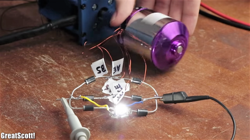
What’s the best way to turn a high-powered brushless DC motor optimized for hobby use into a decent low-RPM generator? Do you take a purely mechanical approach and slap a gearbox on the shaft? Or do you tackle the problem electrically?
The latter approach is what [GreatScott!] settled on with his BLDC rewinding and rewiring project. Having previously explored which motors have the best potential as generators, he knew the essential problem: in rough terms, hobby BLDCs are optimized for turning volts into RPMs, and not the other way around. He started with a teardown of a small motor, to understand the mechanical challenges involved, then moved onto a larger motor. The bigger motor was stubborn, but with some elbow grease, a lot of scratches, and some destroyed bearings, the motor was relieved of both its rotor and stator. The windings were stripped off and replaced with heavier magnet wire with more turns per pole than the original. The effect of this was to drive the Kv down and allow better performance at low RPMs. Things looked even better when the windings were rewired from delta to wye configuration.
The take-home lesson is probably to use a generator where you need a generator and let motors be motors. But we appreciate [GreatScott!]’s lesson on the innards of BLDCs nonetheless, and his other work in the “DIY or buy?” vein. Whether you want to make your own inverter, turn a hard drive motor into an encoder, or roll your own lithium battery pack, he’s done a lot of the dirty work already.
Thanks for the tip, [baldpower].


Reducing the field intensity actually increases the Kv of the motor by reducing the back-EMF generated, which is why motors designed for high speed are terrible generators.
It’s a bit counter-intuitive, but the stronger the magnets you put in the motor, the slower it turns (but the more torque it makes).
Stepper motors often make the best generators if you’ve got enough torque to keep them turning.
Wouldn’t think they’re the most efficient though? They’re not self-magnetizing, so you need to provide the field current somehow or rely on the remanent field, which produces varying results.
As long as you keep it turning. Nothing beats the current and relatively high voltage at faily low speeds. Enough for a reasonable shock even if twisted with your fingers. Most providing a good fourty five to fifty volts without any issues.
I remember building a “batteryless LED flashlight” using the stepper motor from an old floppy drive and some “high brightness” red and green LEDs. That was about 20 years or so ago, before white LEDs were commonly available.
If it is a switched reluctance motor, then the amount of voltage and current you get is highly variable because the rotor is not supposed to be permanently magnetized – it just is. If you bump the motor hard, or run it hot, too fast, etc. the magnetization will change and your generator changes behavior, usually for the worse.
If it’s actually some variant of a BLDC motor, then there’s no issues. Floppy drive motors typically have permanent magnets.
One easy way to get a generator is to use the front part of a cordless drill as it can make useful amount of power at a usable voltage with a hand crank.
I am not sure (it has been some time, since I was learning about motors), but an electrical approach would be to reprogram ESC to act as a rectifier.
An ESC will act a rectifier without reprogramming due to the body diodes in the power FETs
In regen mode, they actually use a clever trick to extract power at much lower RPMs than would otherwise be possible.
http://techno-fandom.org/~hobbit/cars/boost-hack/
“hobby BLDCs are optimized for turning volts into RPMs”
Really? Really? I am very disappointed in you, young man….
Care to explain your issue instead of just chiding the author like an old schoolmarm?
Yes, yes, it’s the current but, actually this is correct in that they are designed specifically to convert rather low voltages into very high rpm which is what the author was referring to.
“replaced with heavier magnet wire with more turns per pole than the original”
How does this work? In the video the new wire is indeed of heavier gauge, but how could it possibly fit more turns than the thinner wire? Or is the old wire actually multiple wires in parallel, litz-style?
Keep the wires as is, just add 3 polarity independent synchronous boost converters. Then you have efficiency, regulation and if you wish an MPPT feature.
Couldn’t you switch between delta and wye on the fly for regenerative systems? Or is there something obvious that I am missing?
Start with a BLDC gimbal instead and you’ll get usable voltage right off. They use much thinner wire and a lot more wraps for a low KV right out of the box.
The essential problem is that motors and generators are more efficient and exponentially more effective at higher speeds relative to coil and magnet. So you could increase the poles or the RPM. Rewinding makes things cheaper and simpler at the cost of power output and efficiency.
No?