With the high availability of modular components and incredible wealth of information and tutorials online, it’s now easier than ever for hackers and makers to assemble complex electronic projects without getting bogged down with the theory behind it all. But the downside is that the modern electronic hobbyist often doesn’t have as deep an understanding of the low-level concepts that they would have if they had to build everything from scratch. This can be a problem when they try diagnosing and repairing faults, or when they start to branch out into reverse engineering.
 Which makes “Building Blocks” by [David Christensen] a very compelling series. Every week he will be demonstrating a new circuit on his blog, complete with a plain English explanation of how and why it’s used. In this first installment of the series, he’s tackling a concept most of us have seen when poking around in more complex electronic devices, but maybe never really gave much thought to: the negative rail.
What exactly is the negative rail, anyway? It’s pretty easy to understand the positive rail in a circuit and its relation to ground; even multiple positive rails, such as in devices which use both 5 V and 3.3 V, are simple enough to wrap your head around. Unfortunately when something drops below that logical 0V reference, it isn’t quite as intuitive. But as [David] explains, the negative rail in a circuit is critical for dealing with bipolar signals, such as audio, which ride above and below the 0 V center point.
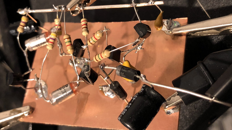
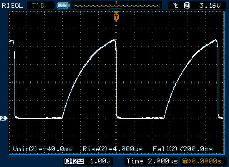
[David] goes over a few methods used to create the negative rail, from the classic center-tap transformer to using a buck-boost converter. But not content with just describing how these circuits work, he walks the reader through the creation of a charge pump circuit that you can drop into your next project if you find yourself in need of the elusive voltage. After explaining and diagramming it, he builds the circuit on a scrap piece of copper clad board and puts it through some benchmarks to prove it matches the theory he laid out.
If you’re in the mood for more negative talk, check out the battle our very own [Steven Dufresne] had with voltages of varying polarity when building his BB-8 robot.


More esoteric than the ‘negative rail’ is the ‘virtual ground’
http://www.eevblog.com/images/shirts/IonlyGiveNegativeFeedback20.jpg
+1
It’s fun when you find 30+ year old circuit diagrams where power rails are labelled +12V and -12V and you have to figure out whether it’s 12V to negative ground, or a 12V 0V -12V split rail supply.
It’s always relative to a 0V ground. The important thing – and maybe I didn’t push the point enough in the article (yep, I’m the original author) is that what we call ground is always definitionally 0V. It’s a nice shorthand.
One analogy I came up with, is that ground is where you put the black probe of your mental multimeter. That’s all. Voltages are always between one point, and ground is the one we’ve chosen to be the referece point!
RW was saying that the standard has changed over time. There was a time when a PSU or some form of supply had a potential difference of only 12 volts but was marked as +12v and -12V.
That’s a pretty crusty old way to do it for sure. What I’ve seen that was somewhat common – and is in specialised applications like some types of ECL logic, is a negative rail and ground.
This, on the other hand, was because in those days, the ground usually had a nice PCB plane or rail, and was typically less noisy than any of the supply rails, which didn’t have as nice PCB tracework. So it made sense to call the positive of the two ground, and the negative, well, a negative rail (the logic levels weren’t flipped – a logic low was typically more negative than a logic high).
So yeah, there’s been all sorts of trickeries around this!
Look at a 9V battery, the terminals are marked + and -.
You will also find many power supplies, where zero volts is *not* ground. These typically have three output terminals:positive, negative, and ground. They also have a shorting plate, allowing you to tie the positive OR negative output to ground.
The extended version of these supplies have four terminals: positive, negative, zero and ground. Useful if you are playing with floating [isolated] circuits.
Once I was working on whey separator. It had power supply positive terminal equal 0V. Diffucult to trouble shoot because it also had other one with positive terminal +24V. Until now I was wondering how was it possible? It looks that vendors technician must have accidentaly tie positive to ground. It was my first job and I had no idea how to investigate that. I was sure it was a faulty ps. Fortunatelly I was smart enough to figure out that positive does not have to be 24V to ground but to negative.
Thanks for pointing that out.
What about floating GND supplies? =D
*elusive voltage. It’s very real, just hard to grasp.
Thanks! Fixed.
But on the other hand, no voltage is real: only voltage differences. So maybe “ground” is both.
Anyone want to buy a -9 V battery?
Not unless you are paying me $2 a piece because it is an anti-battery with current flowing backwards. :P
Haha, you pay to have things brought to you, and you pay to have things taken away. Work is work. :P
Electron flow is backwards so is a ‘+’ rail the negative potential????
Electron Current vs. Conventional Current
https://www.mi.mun.ca/users/cchaulk/eltk1100/ivse/ivse.htm
The words Negative and Positive are entirely arbitrary. These words existed prior and had the meanings of “to subtract” and t”to add”.
An electron has a “Negative” charge, this to is arbitrary.
Atoms stay (relatively) still and electrons move from one atom to the next in a flow. This is an observation and is not arbitrary.
Electrons (which have an arbitrary negative charge) flow from the battery negative to the battery positive in a direction that is opposite to all the arrows on a circuit diagram.
“If you’re in the mood for more negative talk, check out…” the usual Hackaday comments! :-P And there’s another just to prove it! :-)
Quit railing about it…
B^)
He could… potentially.
Let’s ground our current arguments and instead try to supply positive comments from here on out …
I think your comment is very biased.
Guilty as charged!
In large motor controllers (Like those used in Electric Vehicles), the gates of IGBTs and MOSFETs (N-type) are driven negative to turn them off.
IGBT gates have to be driven negative for quick turn off.
MOSFETs do not have to be driven negative to turn off, but doing so prevents ground bounce (noise), or induced voltages from accidentally turning them on.
This is a good example of a necessity for a negative voltage. In this high power application deriving a false ground would be inefficient, require a large regulator stage, and also limit the power available to the load. Deriving a negative rail for the low power requirement of the gate is trivial by comparision.
“The Negative Rail Explained”
What, exactly, needs explaining? Why all the words?
This mysterious “negative rail” is a power supply which outputs a negative voltage, with respect to ground. There’s the whole article right there.
How about a complementary follow-up “article” explaining “The Positive Rail”? My clock, with a PMOS chip has, as its main supply, -12 volts. The clock also has a light-duty +12 v. supply for biasing purposes. I am baffled by the existence of a positive “rail”. I can NOT understand it,
Just as I CAN NOT understand the use of negative voltages (totally) in DEC’s original ‘Flip-Chip’ modules. PLEASE give us a tutorial on “The Positive Rail”, so we can all understand the use of positive–with respect to ground–voltages.
With any luck at all, you can make a ‘best-seller’ book out of this.
And there’s a classic example of negative railing on and on.
We’ve found the
ideal personexpert to explain “The Positive Rail”.Back in the days of much op-ampery, a voltage-doubler with ground at the point between the caps uses a plain transformer and only two diodes. http://hyperphysics.phy-astr.gsu.edu/hbase/Electronic/voldoub.html Regulate or not depending on the op-amp and the application. This was the simplest way until the IL7760 came out https://doc.diytrade.com/docdvr/108715/17365069/1290092965.pdf
Back in the day when I built cmoy headphone amps for fun I used to use a resistive divider (in the form of matched resistors or even a multiturn pot) from a single positive supply to generate a virtual ground point at half supply and then buffer that ground through a single supply opamp wired as a voltage follower so it could source/sink current without dipping the virtual ground asymmetrically towards one rail or the other.
That’s still the best way to make a split supply for op-amps. If there needs to be a power stage then you can used a full bridge (duel totem).
Indeed. That’s your classic rail splitter. Unfortunately, it /can/ be unstable when buffered, so some moderate-ESR decoupling is warranted.
For more current gain, you can of course use a “class B” DC push/pull pair of transistors. Especially if you need to capacitively couple in several sources at line-ish impedances (your reference starts to be loaded down…)
However, it does presuppose you’ve got a large enough voltage to begin with. Not all op amps are rail-to-rail input or output, and if you’ve got a single +3.3V or even +5V rail and the common mode is from Vee+1.5 to Vcc-1.5, you’ve got a 0.3V or 2.3V range, which is a tad… slim-line for some purposes.
Hence why it’s sometimes useful to make a basement under your ground floor, as it were… As long as it’s not noisy, of course. And that’s what I tried to do.
As always, though, the application suggests the solution. There are no silver bullets in circuit design :-)
I used a single op-amp and a big NPN and PNP to regulate. Adding this to the doubler gets a pretty good supply with minimal parts. The transistors were driven by the current sinking of the OA power pins similar to this https://www.nutsvolts.com/uploads/wygwam/NV_0801_Marston_FIGURE11.jpg
But the doubler fits the topic and is very low impedance.
That works as a”quick and dirty” for low frequency AC signals. The problem at higher frequencies is the time it takes the op-amp to transition (slew rate) across the 1.2V difference between the base voltages. This causes flat spots and overshoot.
A simple fix is to put diodes between the op-amp and bases and some series bias resistors, Then you will also need some emitter resistors to limit the quiescent current.
For higher current output just mirror the same circuit so there is no ground in the output path.
It is a supply to power op-amps. In fact, usually seismic stuff where 10Hz would be the max, or mechanically chopped optical tasks with 10 to 60 Hz. Likewise, second order DEQ solutions – also slow. Filter caps on the output handle transient current demand. Op-amp power supply rejection takes care of the rest.
Talking about the 7660, i recently found the LM2662 that can supply 200mA @-5V and can also act as a voltage doubler. Costs 0,99$ from China (works but i did not check the maximum current on this unit).
+1 I bought some last year and super handy chip.
A lot of legacy telecoms equipment runs at -48v
If i remember correctly they chosed a negative voltage for corrosion protection on the landlines or something?
The one that gets me are those old Kimball organ designs that had lower neg rail and a higher positive rail. Something like -10 and +15 or +20 used in op amp audio processing. This was a leftover from earlier discrete logic if I remember the earliest stuff I remember seeing in books. Very messy.
Most of my things have already have a microcontroller that can easily serve the role of the oscillator in this circuit. So the circuit can get even simpler. You also get a free software enable, as well as precision placement of the generated noise…
I’ve used a MAX232 a couple of times as a +/-15v supply for opamps, it works surprisingly good, no noise even on a phono preamp at full volume.
Iirc the MAX232 only does +-8,5V or something? Or maybe the one i have is a fake?
No, you’re right, my bad. It still worked nice tho
The link is dead now. Too bad.