The ESP-01 launched the ESP8266 revolution back in 2014, and while today you’re far more likely to see somebody use a later version of the chip in a Wemos or NodeMCU development board, there are still tasks the original chip is well suited for. Unfortunately, they can be tricky to use while prototyping because they aren’t very breadboard friendly, but this adapter developed by [Miguel Reis] can help.
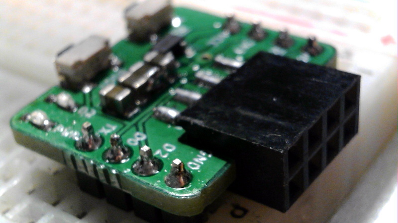
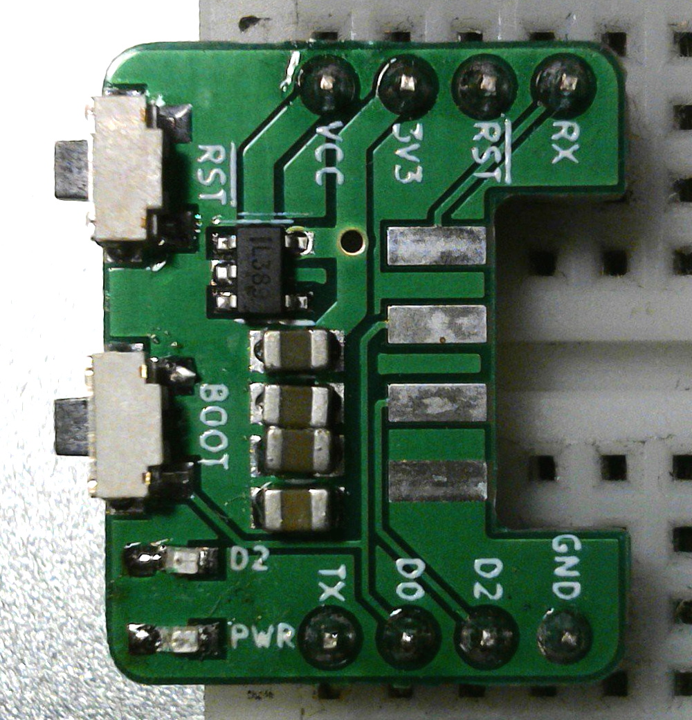 Of course, the main issue is the somewhat unusual pinout of the ESP-01. Since it was designed as a daughter board to plug into another device, the header is too tight to fit into a breadboard. The adapter that [Miguel] has come up with widens that up to the point you can put it down the centerline of your breadboard and have plenty of real estate around it.
The second issue is that the ESP-01 is a 3.3 V device, which can be annoying if everything else in the circuit is running on 5 V. To get around this, the adapter includes an SPX3819 regulator and enough capacitors that the somewhat temperamental chip gets the steady low-voltage supply it needs to be happy.
[Miguel] has released the schematics and board files so you can spin up your own copy of the adapter, but they’re also available for around $3 USD from his Tindie store.


You are still using 5V logic?
It tastes stronger.
Unrelated to the subject of the post, but, surely I can’t be the only one annoyed by hackaday.io’s image viewer? Why do I _have_ to click on the picture in order to see all of it? I get that it’s an aesthetic choice to have it take up less space, but it’s also a classic case of form over function.
Its just .io
Ignore links to it. The interfarce has been horrible since day one. (unless you are addicted to swiping all day and directions) even a simple mediawiki page is better in layout. But alas. Things are the way they are an we have to live with them.
I truely feel sorry for the team that thought this was a great way to present information. Everything neat sorted: files with files, pictures with pictures and text with text. Nicely dispersed with way too much empty space.
Oh well. This was my monthly rant again. Sorry for that.
Meanwhile I have to do a writeup on the film holder design I made for ultra large photography using freecad to make a parametric design outputting technical drawings in one go. But so much to do…
Very true, bad since day one
Indeed Easy….. but at 3USD only useful if you are prototyping a lot of ESP-01’s. If only a few better get a Wemos for that price :-)
I looked at this and the plenty of real estate around it looks to be one row of holes on each side. It also lacks the FTDI chip. If it had everything you needed on it I would like that. It would be cool to have a more proper “carrier” for the 8266 modules. But lacking more space around it, I am good with the set up I have now, with the FTDI that I need anyway, a 5V/3.3V regulator that plugs into the breadboard, and a bundle of M-F jumpers with the F side tie wrapped together. This fits the 8266 amazingly well and I can have 4 holes free in each spot I plug into. IMHO if you put an FTDI on it and the regulator, and make it so it is long and skinny and gives you more holes I would try a couple.
On a side note has any outfit in China ever sold a version of the -01 that has an option (juper, solder blob etc) to connect GPIO16 to RST for low power work. I can nix the LED’s with side cutters but getting a wire onto a chip pin is not something I wanna try to do in quantity. It looks like it would be so easy at the factory…
There are similar adaptors on Aliexpress for 1USD:
https://fr.aliexpress.com/item/32827244081.html
I have one I had to hack because the reset functionality was not supported!:
https://www.instructables.com/id/USB-to-ESP-01-Board-Adapter-Modification/
Well that board isn’t really breadboard friendly is it?
Seems like this board could be really useful