There comes a time in every hardware hacker’s career during which they first realize they need a negative voltage rail in their project. There also comes a time, usually ~10ms after realizing this, when they reach for the Art of Electronics to try and figure out how the heck to actually introduce subzero voltages into their design. As it turns out, there are a ton of ways to get the job done, from expensive power supplies to fancy regulators you can design, but if you’re lazy (like I am) you might just want a simple, nearly drop-in solution.
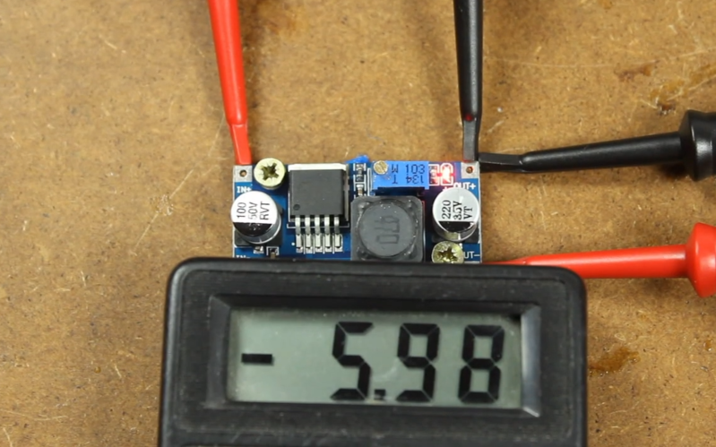
[Filip Piorski] has got you covered there. In a recent video, he demonstrates how to turn a “China Special” $1 buck converter from Ebay into a boost-buck converter, capable of acting as a negative voltage supply. He realized that by swapping around the inputs and outputs of the regulator you can essentially invert the potential produced. There are a few caveats, of course, including high start-up current and limited max. voltages, but he manages to circumvent some of them with a little clever rewiring and a bit of bodge work.
Of course, if you have strict power supply requirements you probably want to shell out the cash for a professionally-built one, or design one yourself that meets your exact needs. For the majority of us, a quick and easy solution like this will get the job done and allow us to focus on other aspects of the design without having to spend too much time worrying about the power supply. Of course, if power electronics design is your thing, we’ve got you covered there, too.
Thanks to [Bornach] for the tip!


There is a much easier way to accomplish this, depending on what your loads need.
For example, if you need +/- 5V for an op amp just regulate to +10v and set up a 5V voltage divider. And then using your +5V as a reference, you now have a +/- 5V supply. The benefit is you have one less regulator to fail.
Problem is the op amp rails draw current and that affects the load connected to the voltage divider. Best way, IMO, is to use two batteries in series and connect the node in the middle of the batteries to reference.
Of course this can be done, but it’s not a negative voltage. It’s a “single supply” OPV circuit. Often done and nice, but it has it’s limitations.
Sure, every solution has its limitations. I was just proposing an alternate to building in an additional potential failure point into your design. Voltage dividers rarely fail.
You have to understand your load including it’s power supply noise tolerances before designing any power supply.
Very clever! But I wouldn’t call it the cheapest or easiest.
You can wire a 555 timer (or any gate) as an oscillator, and use a few diodes and capacitors wired up as an inverting voltage doubler or tripler. Gates can deliver 5-10ma; a 555 more like 50-100ma.
You can use a 7660 to turn +5v into -5v.
You can use the internal charge pump in a MAX232 simply as a negative voltage supply.
You can use just about any switching regulator chip to supply a negative voltage. Some of these are mighty cheap.
You can use an old “wall wart” out of your junk box as your negative supply. It’s probably free. :-)
* Positive and Negative Charge Pump Circuit Using 555 Timer
https://circuitdigest.com/electronic-circuits/positive-and-negative-charge-pump-circuit-using-555-timer
Great hack!
if your incoming supply can handle the inrush/peak current, its great, but for high-gain sensitive circuitry, i prefer a complete “balanced” supply, to keep the + and – voltages as close to each other as possible (for ground-referenced DC-coupled signals)
of course this trick(hack) can be used with a post-tracking regulator to tweak the neg. to mirror the pos.
for balanced low-current power for ground-referenced OP-AMPs, i prefer to roll my own:
1) 34063 wired as flyback, traditional passive rectification, slightly less efficiency then sync.-rect. but less EMI/RFI
2) custom transformer wound on core from power inductor, three outputs, 100uH
3) three outputs should be mechanically parallel for ideal regulation and tracking(tri-fillar?) but not same length/voltage
4) one output wired as ground-referenced feedback winding, with minimum load such as 3.3v or 5v logic
5) two other outputs wired as floating bi-polar for +/- with red LEDs (in series) wired as zeners, red is least noise (at 20ma)
6) zener-LEDs should be doubled-up for higher current during supply andor logic/computer bootup.
6) slowly increase fed-back regulation voltage until LED-zeners pass about 15mA
7) floating ground links to system ground at amplifier star-ground or system star-ground.
8) when computer (powered by feedback winding) goes into sleep, zener-LEDs go dim and stop wasting so much power.
its a design needing fine tuning but serves as a drop-in replacement for a normally wall-outlet powered design that originally used a converter with multiple transformer outputs (+12v +3.3v +6v +6.5v -6.5v), a battery supplies the +12v and the converter.
I’d go for the 7660, a few parts and you are good to go. Same volts just negative.
If the voltage is negative, shouldn’t it be a “voltage drain”, not “voltage supply”?
:-)
There are no negative or positive voltages, only voltage differences.
For example, put your meter’s black lead on ground of a 5V supply, you measure +5V at the output. But put your meter’s black lead on the output and your meter’s read lead on ground and you now measure -5V.
It’s the same potential or voltage difference. The +/- is determined by your reference point.
It’s the same with a negative supply. A +/- 5V power supply is really just a 10V supply with the reference point (or the ground) set to the middle. So, from that reference point you measure +5V on the + side and you measure -5V on the low side.
But measure across both outputs you get 10V, + or – depending on where you place your meter’s black lead.