China Loves Battery Swapping EVs, But Will They Ever Make It Here?

Electric vehicles promise efficiency gains over their gas-fuelled predecessors, but the issue of recharging remains a hurdle for many eager to jump on board with the technology. The problem is only magnified for those that regularly street park their vehicles or live in apartments, without provision to charge a vehicle overnight at home.

Battery swapping promises to solve that issue, letting drivers of EVs change out their empty battery for a freshly charged one in a matter of minutes. The technology has been widely panned and failed to gain traction in the US.

However, as it turns out, battery swapping for EVs is actually thing in China, and it’s catching on at a rapid rate.

Continue reading “China Loves Battery Swapping EVs, But Will They Ever Make It Here?”

Mystery Effect Causing LEDs To Glow During Reflow

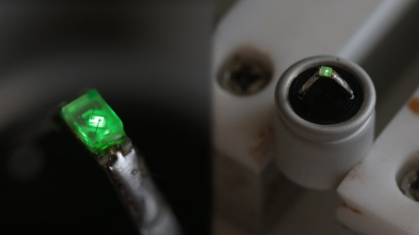
Sometimes you notice something small that nevertheless you can’t explain. [Greg Davill] found himself in just such a situation this week when he noticed some green LEDs glowing dimly when reflowing some boards. Naturally, [Greg] set out to investigate.

The green LEDs were wired up as power indicators, and [Greg] suspected that the polymer caps on the board might be generating a small current somehow that was causing the LEDs to light up ever so slightly. A simple test hooked a polymer cap directly up to a multimeter. When warmed with a heat gun, the meter showed a small current “in the 5-10 uA range.”

Going further, [Greg] soldered an LED to the cap and once again heated it up, this time to 100° C. The LED  glowed, continuing to do so for around 60 seconds with heat removed. The mystery also grew deeper – [Greg] noticed that this only happened with “fresh” capacitors. Once they’d been through one heat cycle, the caps would no longer light an LED when warmed up.

It’s a curious case, and has many speculating as to the causative mechanism on Twitter. Explanations from thermoelectric effects to chemical reactions inside the capacitor. If you’ve got the inside scoop on what’s going on here, don’t hesitate to let us know in the comments. Meanwhile, check out some of [Greg]’s best work – a glowing D20 dice featuring a whopping 2400 LEDs.

[Thanks to J Peterson for the tip!]

A Guide To Milling PCBs At Home

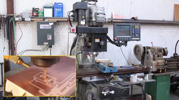
If you keep up with various retro vacuum tube projects, you probably have run across [UsagiElectric] aka [David]’s various PCBs that he makes on his own Bridgeport EZ-Track 3-axis milling machine — massively oversized for the job, as he puts it. In a recent video, [David] walks us through the steps of making a sample PCB, introducing the various tools and procedures of his workflow. He points out that these are the tools he uses, but the overall process should be similar no matter what tools you use.

  • Logisim to validate logic designs
  • TINA-TI, Texas Instrument’s version of the TINA SPICE simulator
  • DesignSpark PCB for schematic entry and PCB layout
  • FlatCAM, a computer-aided PCB manufacturing tool

For this video, [David] makes a half-adder circuit out of four vacuum tubes plus a seven-segment VFD tube to show the combined sum and carry outputs. Momentary switches are used to generate the two addends. Using this example, he proceeds to design, simulate, build and demonstrate a working circuit board. We like his use of the machined pin socket inserts for building a vacuum tube socket directly into the board.

Now this process isn’t for everyone. First of all, a Bridgeport mill is a pretty good sized, and heavy, tool. That said, these procedures should adapt well to other milling machines and engravers. We should point out that [David] is making boards mostly for vacuum tubes, where circuit trace width and spacing distances are generous. If you’re planning to make home PCBs for a 273-pin PGA chip, this isn’t the technique for you.

It seems that the bulk of [David]’s vacuum tube PCBs are single-sided, and reasonably so. They use wire links here and there to jump over traces. Adapting this process to double-sided PCBs is doable, but more complex. Are you milling double-sided boards in your lab? If so, let us know about it in the comments below.

Continue reading “A Guide To Milling PCBs At Home”