[Mellow_Labs] picked up a few LiDAR matrix sensors and found them very exciting. While a normal time-of-flight sensor can accurately determine a range, the matrix sensor is like an array of 64 sensors that can build a 2D map of distances from 2 cm to 3.5 m. [Mellow] wanted to add the sensor to his robot to help it see what was in front of it. You can see how it worked out in the video below.
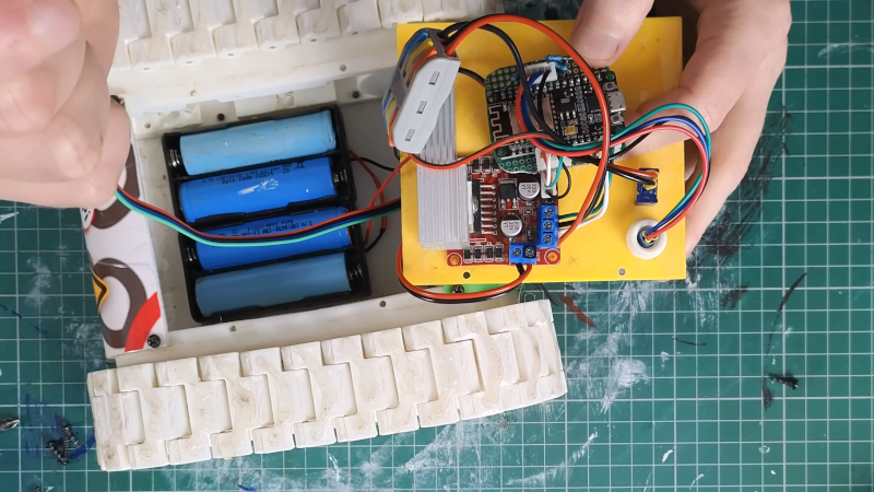
The robot in question is Zippy, a 3D printed tank-like robot with an ESP32. By default, the robot requires control inputs, but using the sensor will enable autonomous operation. For good or ill, the sensor mounted to Zippy was seeing the floor with about half of the rows. That means about 50% of the data went to waste. However, we think having a robot be able to see the floor in front of it might be a good thing.
[Mellow] used an LLM to write most of the code, so there were a number of iterations required to get things working. This required decimating even more of the data from the sensor. Still, pretty impressive.
Want to learn more about ToF sensors? Or if you want to focus on the practical, there’s code you can borrow.


@03:10 “SEN0628 Matrix Lidar” on the whiteboard. (That finds the DFrobot PCB, but not the sensor itself)
@04:34 I can see the outline of his head and arm, but when he moves away (very briefly) Two pixels seem to be stuck (Values: 833 and 655). For the rest, I find his way of presenting very chaotic (not in a good way) I scanned though the rest of the video, but he’s mostly playing with his tracked robot, and there is very little shown of what this sensor can do.
On itself, it’s an interesting sensor, and I want to see more of it’s capabilities. Hold some objects in front of it. Can it see the hole in the teacup from the beginning? Does it do small spot measurements for each location, or does it doe some averaging over larger areas? (I.e. what happens if a small object moves at some distance (a fly for example).
If a big object with a sharp edge (book) move slowly, do the values then “jump” from “far away” to “close” or is there a coarse gradient? It would be interesting to see whether wobbling the sensor can be useful to enhance resolution.
When I read the youtube comments, then a lot of them hint that his vibe coded AI slop is the main reason it does not work properly.
Combine that, and it’s not a channel I find interesting enough to see more from. It’s just another minimum effort video that is barely good enough to get some advertisement money.
VL53L7CX https://www.st.com/en/imaging-and-photonics-solutions/vl53l7cx.html
940 nm source
SPAD array with 4×4 or 8×8 separate zones
60° x 60° field of view
a measly 60 Hz update rate
<3.5m range with white target, darkness
~0.25m range with 5klux and gray target (meh)
What do you expect from a sensor that costs $20? That’s the price many single-point ToF sensors cost.
I’ll stick with my hacked Kinect, thanks.
More vibe code nonsense.
With regards the stuck “pixel” values the company website says a firmware update fixes that.
The HaD post is good as it brought the sensor, and the company, to my notice – orders are in. But the video’s use of AI to make the code is not of interest – it just doesn’t teach me anything other than how to ask someone else of variable ability to do the work for me. Not that I’m opposed to paying someone/thing else to do a job I have no interest in (like painting my house or fixing my car). Bah – where was I? oh yes, there is a new firmware available if you have the one with the brass legs. The black legs version should already be loaded with it.