OLED display, blue LED and Smartcard

Developed On Hackaday: Olivier’s Design Rundown

The Hackaday writers and readers are currently working hand-in-hand on an offline password keeper, the Mooltipass. A few days ago we presented Olivier’s design front PCB without even showing the rest of his creation (which was quite rude of us…). We also asked our readers for input on how we should design the front panel. In this new article we will therefore show you how the different pieces fit together in this very first (non-final) prototype… follow us after the break!

Continue reading “Developed On Hackaday: Olivier’s Design Rundown”

Extracting Gesture Information From Existing Wireless Signals

A team at the University of Washington recently developed Allsee, a simple gesture recognition device composed of very few components. Contrary to conventional Doppler modules (like this one) that emit their own RF signal, Allsee uses already existing wireless signals (TV and RFID transmissions) to extract any movement that may occur in front of it.

Allsee’s receiver circuit uses a simple envelope detector to extract the amplitude information to feed it to a microcontroller Analog to Digital Converter (ADC). Each gesture will therefore produce a semi-unique footprint (see picture above).  The footprint can be analyzed to launch a dedicated action on your computer/cellphone. The PDF article claims that the team achieved a 97% classification accuracy over a set of eight gestures.

Obviously the main advantage of this system is its low power consumption. A nice demonstration video is embedded after the break, and we’d like to think [Korbi] for tipping us about this story.

Continue reading “Extracting Gesture Information From Existing Wireless Signals”

OLED display, blue LED and Smartcard

Developed On Hackaday: The Top PCB Dilemna

The Hackaday community offline password keeper is slowly coming together. A few days ago we received the top PCB for Olivier’s design (shown above). If you look at the picture below, you may see the problem we discovered when opening our package: the soldermask was the wrong color! Given the board is meant to be placed behind a tinted acrylic panel, this was quite a problem…

After using some spray paint, we managed to get to the point shown in the bottom left of the picture. The next task was to find the best way to illuminate the input interface with reverse mount LEDs. Using a CNC mill we machined openings (top right PCB) but also removed some epoxy on both PCB’s sides, thinking it would provide a better light diffusion. We then wrote part of the Mooltipass PWM code and took these pictures:

Continue reading “Developed On Hackaday: The Top PCB Dilemna”

ISPnub – A Stand-Alone AVR In-System-Programmer Module

[Thomas] tipped us about his latest project: a stand-alone AVR programmer module named ISPnub. As you can see in the picture above, it is a simple circuit board composed of a main microcontroller (ATmega1284p), one button and two LEDs. Programming a target is a simple as connecting the ISPnub and pressing the button. The flashing operation success status is then shown using the green/red LED.

ISPnub gets its power from the target circuit so no external power supply is needed. It works over a wide voltage range: 1.8V to 5.5V. The module also features a programming counter which can be used to limit the number of programming cycles. A multi-platform Java tool is in charge of embedding the target flash contents with the ISPnub main firmware. The complete project is open source so you may want to check out the official GitHub repository for the firmware and the project’s page for the schematics.

Developed On Hackaday: 2 Days Left To Submit Your Design!

We’re sure that many of Hackaday readers already know that one of the two main components of the Mooltipass project is a smart card, containing (among others) the AES-256 encryption key. Two weeks ago we asked if you’d be interested coming up with a design that will be printed on the final card. As usual, many people were eager to contribute and recently sent us a few suggestions. If you missed the call and would like to join in, it’s not too late! You may still send your CMYK vector image at mathieu[at]hackaday[dot]com by sunday. More detailed specifications may be found here.

In a few days we’ll also publish on Hackaday a project update, as we recently received the top and bottom PCBs for Olivier’s design. The low level libraries will soon be finished and hopefully a few days later we’ll be able to ship a few devices to developers and beta testers. We’re also still looking for contributors that may be interested in helping us to develop browser plugins.

The Mooltipass team would also like to thank our dear readers that gave us a skull on Hackaday projects!

Using SIMMs To Add Some Extra RAM On Your Arduino UNO

A Single In-line Memory Module (SIMM) is a type of memory module containing Random Access Memory (RAM) which was used in computers from the early 1980s to the late 1990s (think 386, 486, Macintoshs, Atari STE…). [Rafael] just made a little library that allows you to interface these modules to the Atmega328p-based Arduino UNO in order to gain some memory space. His work was actually based on the great Linux on the 8bit ATMEGA168 hack from [Dmitry Grinberg] but some tweaks were required to make it work with [Rapfael]’s SIMM but also to port it to the Arduino platform. The 30-pin SIMM shown above is capable of storing up to (hold on to your chairs…) 16MB but due to limited amount of available IOs on the Atmega328p only 256KB can be used. Our guess it that an SPI / I2C IO extender could lift this limitation. A quick (shaky) video is embedded after the break.

Continue reading “Using SIMMs To Add Some Extra RAM On Your Arduino UNO”

Building An Inductive Loop Vehicle Detector

[Trax] was asked by a friend to build a device that could detect the presence of a car in front of his garage gate for it to open automatically. After searching the web for such a project and trying many of them, he decided to build his own detector based on an induction loop. As you may have guessed, this kind of detector works by detecting an inductance change in a wire loop (aka coil) buried in the road. Having a car pass several inches on top of it produces such an effect.

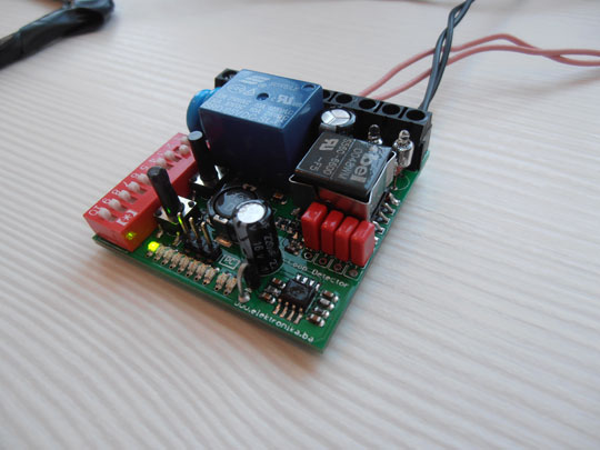
[Trax]’s write-up shows a very well thought and professional design. All the detector parameters can be adjusted using DIP switches and buttons: detection type (presence/pulse), signal filtering, main frequency and sensitivity. The wire loop is isolated from the main sensor electronics using a 1:1 isolation transformer and a Colpitts oscillator is used to drive the latter. Moreover, gas discharge tubes are also used for lightning protection.

The change in inductance translates to a change in resonant frequency which is later detected by the main microcontroller. The board is 24V AC powered and a diode bridge + LM2596 SMPS step-down converter are in charge of generating the required +5V in an efficient way.

As if this was not enough, [Trax] also made a PC-based tool that can change other platform settings using a serial connection. All the resources can be downloaded from his website and a few videos are embedded after the break.

Continue reading “Building An Inductive Loop Vehicle Detector”