Integration Taught Correctly

[Math the World] claims that your calculus teacher taught you integration wrong. That’s assuming, of course, you learned integration at all, and if you haven’t forgotten it. The premise is that most people think of performing an integral as finding the area under a curve or as the “antiderivative.” However, fewer people think of integration as adding up many small parts. The video asserts that studies show that students who don’t understand the third definition have difficulty applying integration to real-world problems.

We aren’t sure that’s true. People who write software have probably looked at numerical integration like Simpson’s rule or the midpoint rule. That makes it pretty obvious that integration is summing up small bits of something. However, you usually learn that very early, so you’re forgiven if you didn’t get the significance of it at the time.

Continue reading “Integration Taught Correctly”

Integrating sphere test setup

Cannonball Mold Makes A Dandy Integrating Sphere For Laser Measurements

It’s an age-old riddle: if you have a perfect sphere with a perfectly reflective inner surface, will light bounce around inside it forever? The answer is pretty obvious when you think it through, but that doesn’t mean that you can’t put the principle to use, as we see with this homemade Ulbricht sphere for optical measurements.

If you’ve never heard of an Ulbricht sphere, don’t worry — it’s also known as an integrating sphere, and that makes its function a little more apparent. As [Les Wright] explains, an integrating sphere is an optical element with a hollow spherical cavity that’s coated with a diffusely reflective coating. There are two ports in the sphere, one for admitting light — usually from a laser — and one for light to exit. The light bounces around inside the sphere and becomes perfectly diffuse, and creates a uniform beam at the exit port.

[Les]’ need for an integrating sphere comes from the desire to measure the output of some of his lasers with his Raspberry Pi-based PySpectrometer. Rather than shell out for an expensive commercial integrating sphere, or turn one on a lathe, [Les] turned to an unlikely source: cannonball molds. The inside of the mold was painted with an equally unlikely ultra-white paint concocted from barium sulfate and PVA glue. With a few ports machined into the mold, it works perfectly to diffuse the light from his dye lasers for proper measurements.

Lasers can be an expensive hobby, but [Les] always seems to find a way to make things more affordable and just as good. Whether it’s homemade doorknob caps for high-voltage power supplies or blasting the Bayer filter off a cheap CCD camera, he always seems to find a way.

Continue reading “Cannonball Mold Makes A Dandy Integrating Sphere For Laser Measurements”

Circuit Simulation In Python

Using SPICE to simulate an electrical circuit is a common enough practice in engineering that “SPICEing a circuit” is a perfectly valid phrase in the lexicon. SPICE as a software tool has been around since the 70s, and its open source nature means there are more SPICE tools around now to count. It also means it is straightforward enough to use with other software as well, like integrating LTspice with Python for some interesting signal processing circuit simulation.

[Michael]’s latest project involves simulating filters in LTspice (a SPICE derivative) and then using Python/NumPy to both provide the input signal for the filter and process the output data from it. Basically, it allows you to “plug in” a graphical analog circuit of any design into a Python script and manipulate it easily, in any way needed. SPICE programs aren’t without their clumsiness, and being able to write your own tools for manipulating circuits is a powerful tool.

This project is definitely worth a look if you have any interest in signal processing (digital or analog) or even if you have never heard of SPICE before and want an easier way of simulating a circuit before prototyping one on a breadboard.

FM Signal Detection The Pulse-Counting Way

Compared to the simple diode needed to demodulate AM radio signals, the detector circuits used for FM are slightly more complicated. Wrapping your head around phase detectors, ratio detectors, discriminators, and quadrature detectors can be quite an exercise. There’s another demodulation method that’s not so common, but thankfully it’s also pretty easy to understand: the pulse counting detector.

As [Allan (W2AEW)] notes in the video below, pulse counting is a bit of a misnomer. Pulse counting works by generating a narrow, fixed-width square wave pulse at a set point in the received FM signal’s waveform, usually at the zero-crossing point. Since the frequency of the modulated carrier changes, the duty cycle of the resulting pulse train varies. That means there will be a fixed number of pulses, but by taking the average voltage of the pulse train, we can tease out the original audio frequency signal.

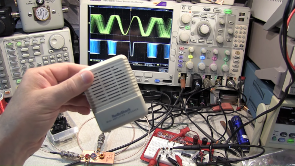
Simple in theory is often more complicated in practice, and [W2AEW] goes into some detail about those complications, such as needing to use a down-converter to make the peak-to-peak frequency deviation in the pulse train more easily detectable. As is his style, he walks us through a test circuit to prove that the theory works in practice. A simple two-transistor circuit generates the pulses at the zero-crossing point, a low-pass filter cleans up the signal, and a cheap audio amplifier reproduces the original audio. It’s a crude circuit to be sure, relying on the stray capacitance of the breadboard to work, but it proves the point and serves as a jumping-off point for further experiments – perhaps using an Arduino to count the pulses?

We always enjoy [W2AEW]’s videos and learn a lot from them. Not long ago we featured another of his videos talking about the mysteries of RF modulation; SSB, anyone?

Continue reading “FM Signal Detection The Pulse-Counting Way”

Calculus In 20 Minutes

If you went to engineering school, you probably remember going to a lot of calculus classes. You may or may not remember a lot of calculus. If you didn’t go to engineering school, you will find that there’s an upper limit to how much electronics theory you can learn before you have to learn calculus. Now imagine Khan Academy, run by an auctioneer and done without computers. Well, you don’t have to imagine it. Thinkwell has two videos that purport to teach you calculus in twenty minutes (YouTube, embedded below).

We are going to be honest. If you need a refresher, these videos might be useful. If you have no idea how to do calculus, maybe these are going to whiz by a little fast. However, either way, the videos have some humor value both from the FedEx commercial-style delivery to the non-computerized graphics (not to mention the glass-breaking sound effects). Of course, the video is about ten years old, but that’s part of its charm.

Continue reading “Calculus In 20 Minutes”

OLED display, blue LED and Smartcard

Developed On Hackaday: Olivier’s Design Rundown

The Hackaday writers and readers are currently working hand-in-hand on an offline password keeper, the Mooltipass. A few days ago we presented Olivier’s design front PCB without even showing the rest of his creation (which was quite rude of us…). We also asked our readers for input on how we should design the front panel. In this new article we will therefore show you how the different pieces fit together in this very first (non-final) prototype… follow us after the break!

Continue reading “Developed On Hackaday: Olivier’s Design Rundown”