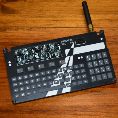
It’s the moment you hard-core hardware nerds have been waiting for: the reveal of the 2025 Hackaday Supercon Communicator Badge. And this year, we’ve outdone ourselves, but that’s thanks to help from stellar collaboration with folks from the community, and help from sponsors. This badge is bigger than the sum of its parts, and we’ve planned for it to be useful for you to hack on in the afterlife. Indeed, as always, you are going to be the final collaborator, so we can’t wait to see what you’ll do with it.
 We’re going out – wide out – on a limb and trying to create a dense mesh network of badges talking to each other at Supercon. It’s going to be like a badge-hosted collection of chat rooms, as connected as we can make them without talking over each other.
You look up a topic, say Retro Computing or SAO trading, punch in the channel number on the numpad, and your badge starts listening to everything going on around that topic. But they also listen to everything else, and repeat anything they hear on to their neighbors. Like IRC, but LoRa.
Continue reading “Announcing The 2025 Hackaday Superconference Communicator Badge”


