Programming A Microcontroller One Bit At A Time

Imagine you’re stuck on a desert island, hundreds of miles away from the nearest person, and you finally have time to finish that project you’re working on. You have a single microcontroller, but you’re lacking a computer and you need to program an ATtiny13. How do you do it? [androidruberoid] figured out how to manually flash a microcontroller (Russian, surprisingly good translation) using just three switches and a lot of patience.

[androidruberoid]’s ATtiny13 – like nearly all Atmel microcontrollers – are programmed using an SPI interface. This interface requires four signals: SCK, a data clock, MOSI, the data line from master to slave, MISO, data from slave to master, and RESET. By connecting these data lines to buttons, [androidruberoid] is able to manually key in new firmware one byte at a time.

This technique of manually programming bits relies on the fact that there is no minimum speed for an SPI interface. In the video after the break, you can see [androidruberoid] manually programming an ATtiny13 with a simple program. It only lights up an LED, but with enough patience he could key in a simple ‘blink a LED’ program.

Continue reading “Programming A Microcontroller One Bit At A Time”

Kickstarter Isn’t A Store Anymore

Over the past few months, we’ve seen an increasing amount of Kickstarter projects making it into the Hackaday tip line. We don’t mind all these emails from people trying to get their Kickstarter project off the ground, but reading through all the emails of people wanting us to pitch their stuff does get a little bothersome.

It looks like our problem of having to go through dozens of Kickstarter hardware projects a week is about to change. Kickstarter is implementing a few new rules for hardware and product design projects. The new rules prohibit product simulations. This means project creators can’t suggest what the product might do in the future. Only what the prototype can currently do is allowed in the Kickstarter project. Also, product renders aren’t allowed. The only pictures allowed on your Kickstarter project are photos as the prototype currently exists.

There’s also another catch for hardware and product design projects: offering multiple quantities of a reward are prohibited. Of course there’s a provision for things that only make sense as a set (building blocks, for instance), but it looks like funding an Arduino-compatible ATtiny85 board and getting multiple boards is out of the question now.

Of course Kickstarter is looking at the long-term, trying to dissuade project creators from taking the money and running off to South America. We’re wondering what the effect will be in the coming months, though; under these rules Ouya wouldn’t have passed Kickstarter’s litmus test, and smaller projects depending on Kickstarter funding for tooling and molds probably wouldn’t either.

The new changes are probably for the best, and will certainly speed up how long it takes us to go through our email. We’re wondering what HaD readers think of the change, so post your thoughts in the comments after the break.

LED Array Uses Ridiculous Amount Of 14-segment Displays

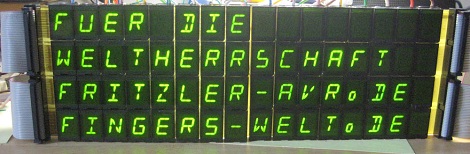
What do you do if you see a bunch of 14-segment LED displays for sale for a penny a piece? [Fritzler], when faced with that conundrum did what any of us would do – he bought 64 14-segment displays and built a huge 16×4 alphanumeric display (German, here’s the translation).

[Fritzler] found a cache of old East German 14-segment displays for €0.01 at electrobi.de (don’t bother, they’re out of stock), and the only thing he could think of was building a gigantic display. He used ULN2803 Darlington drivers for each LED module, but there was still the issue of controlling the entire display.

For that, [Fritzler] decided to make his 16×4 use the same protocol as the Hitachi HD44780 LCD controller. This meant [Fritzler] could wire up his gigantic, power-hungry display to a microcontroller as if it were a simple LCD display.

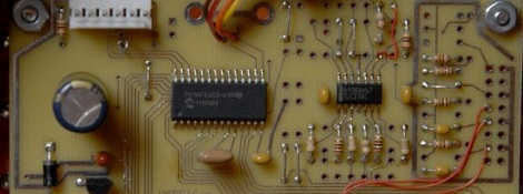
An amazing amount of work went in to the creation of this display, as evidenced by a pair of pictures showing what [Fritzler] had to solder.

Thanks [freax] for sending this one in.

Volumetric Display Projects 200 Million Voxels Per Second

Over the last four years, [Will] and [Gav] have spent their time creating a huge, high-resolution 3D display. The’re just about done with their build, so they decided to offer it up to the Internet in the hopes of people creating new 3D content for their display. They call their project the HoloDome, and it’s the highest resolution volumetric display we’ve ever seen.

The HoloDome operates by spinning a translucent helix around its vertical axis at 20 rotations per second. A pico projector above the helix capable of projecting 1440 frames per second (an amazing device by itself) displays 72 ‘z-axis’ frames for each of the 60 ‘x and y frames’ per second. The result is a 3D display with a 480 * 320 * 72 voxel resolution capable of displaying 20 frames per second.

This isn’t the first time we’ve seen a swept helix used as a volumetric display, but it is by far the highest resolution display of its type in recent memory. [Gav] and [Will] have put their HoloDome up on the Australian crowd-funded site Pozible if you’d like to buy your own, but thankfully the guys have included enough detail on the main site to reconstruct this project.

Check out the video after the break to see the HoloDome in action.

Continue reading “Volumetric Display Projects 200 Million Voxels Per Second”

USBPIC Controls Just About Anything

Over the last few years, [Michael] has been developing a PIC microcontroller board. He calls his project USBPIC, and with the addition of a few FET drivers, H-bridges, and LED drivers his homemade dev board can handle just about anything thrown at it.

[Michael]’s board is build around a PIC18F2455 microcontroller with both an In Circuit Serial Programming header and support for a USB port included. Instead of going for a modular format where the board can expanded through shields or expansion cards, [Michael] decided to make three different versions of the USBPIC.

The TRANS USBPIC includes eight FETs for switching off high current devices totaling 32 Amps. The MATRIX board has twice as many outputs as the TRANS board, but uses ULN2803 or UDN2982 chips for driving smallish-current devices. Finally, the HBSW board takes a TRANS board and replaces four FETs with a an L298 H-bridge chip for driving two DC motors.

For what [Michael] lost in modularity, we think he gained a very tidy microcontroller board capable of driving everything from robots to LED matrix displays.

Mechanical Donkey Kong Features Laser Cut Mario

[Martin] just sent in a project he’s been working on that takes Donkey Kong out of the realm of pixels and sprites and puts our hero Mario into a world made of laser cut plywood.

This mechanical version of Donkey Kong uses an Arduino stuffed into an old NES to control Mario jumping over ball bearing ‘barrels.’ The game starts with 12 of these barrels ready to be thrown by our favorite gorilla antagonist, which Mario carefully dodges with the help of a pair of servos.

This is only the first iteration of [Martin]’s mechanical version of Donkey Kong. The next version will keep the clever means of notifying the player if Mario is crushed by a barrel – a simple magnet glued to the back of the Mario piece – and will be shown at the UK Maker Faire next year.

Although [Martin]’s ideas for a mechanical version of Donkey Kong aren’t fully realized with this build, it’s already a build equal to electromechanical Pong.

Speech Recognition On An Arduino

Speech recognition is usually the purview of fairly high-powered computers chugging along at hundreds of Megahertz with megabytes of RAM. Bringing speech recognition to the low-power microcontroller you’d find in an Arduino sounds like the work of a mad scientist or Ph.D. candidate, but that’s exactly what [Arjo Chakravarty] did. He developed the μSpeech library for the Arduino to allow for speech recognition for a limited set of voice commands.

Where most speech recognition systems use FFT and very fancy math to determine what phonemes a user is saying, [Arjo]’s system does away with this unnecessary complexity in favor of using very, very basic integral and differential calculus.

From [Arjo]’s user guide for μSpeech (PDF warning) we can see it’s possible to connect a small microphone to the analog input of an Arduino and accept voice commands such as ‘left’, ‘right’, and ‘stop’. The accuracy is pretty good, as well – 80% if μSpeech is trying to recognize words, and 30-40% if μSpeech is programmed to recognize single phonemes.

Sadly we couldn’t find a demo video of μSpeech in action, but you’re more than welcome to grab it via github for your own project. Send us a video of μSpeech in action and we’ll put it up.