
Controlling Shift Registers Via SPI

Hack a Day’s very own (and very prolific contributor) [Mike Szczys] put up a great tutorial on how to drive shift registers with an SPI interface.

[Mike]’s earlier tutorial of the 595 shift register goes through the functions of a shift register pin by pin. In a 595, bits for each position in the register are sent over one at a time. Most microprocessors have an Serial Peripheral Interface, and using an SPI bus means a lot less mucking about.

An ATmega168 was used for this build, although most Atmel chips can be made to work as an SPI master device. There are just three wires connecting the microcontroller to the shift register – SER, SRCLK, and RCLK. Like any other shift register setup, the build can be expanded by connecting the QH’ pin of the first 595 to the SER pin of the second.

[Mike] graciously made all the code for his build available. The video after the break is a 16-bit binary counter, a good stopping point before [Mike] rebuilds his Larson scanner/Cylon/Kitt, moving away from a PWM-based build to a register-based one.


Continue reading “Controlling Shift Registers Via SPI” →

Weekly Roundup 11/5/11

In case you missed them the first time, here are this week’s most popular posts:

Our most popular post is about an octocopter that is big enough to hover a person who is perched perilously in the center of an angry array of blades that are counting on Murphy’s law for their chance to taste a little human blood.

Next up is a post about an interesting clock made out of Legos that uses a mechanism similar to the one inside of a combination lock to display the time.

In third place is a post about [Lizzie] and her ‘ball of dub’ that is hard to explain but interesting to listen to.

Next we have a post about how some Occupy Wall Street protesters are generating electricity despite having their generators confiscated. This one is about the hack folks, not the protest. Let’s try to keep the comments civil…

Finally, we have one about a new circuit board put out by the folks who brought us the Beagleboard. This one is called the Beaglebone and it is packing some serious firepower for just $89! We can’t wait to see what our readers come up with these puppies (pun intended)!

Mimicing A Heartbeat In Sound And Electrical Pathways

If you set a cardiac nurse loose on a Propeller microcontroller and some parts you might not know what to expect. But we’re intrigued by the outcome of this project which looks to mimic a heartbeat’s audible and electrical traits. The post about the project is in four parts which are not linked to each other, but you can find them all, as well as a video segment demonstrating the rig after the break.

It seems that this was intended as a Halloween project, but we don’t see why it wouldn’t be interesting any time of year. The Propeller demo board is used to mimic a heartbeat with a pulsing LED. But that doesn’t seem all that awesome, so the sounds of a heartbeat were added to the program to coincide with the blinky light. Here’s where the medical training comes in: the next phase of the process was to lay out an array of LEDs on a breadboard in the shape of the human heart’s electrical system. Now you’ve got a pulsing LED, heart sounds, and a lighted animation showing how the electricity travels through the organ.

To add a little [Poe] to the project there’s also a CdS light sensor. As you approach the project you block some light from getting to the sensor and the heart rate increases.

We think the next logical step is to add a heart rate sensor, so that this can illustrate what your own heart is doing. Boom! Another project ready for the Children’s museum.

Continue reading “Mimicing A Heartbeat In Sound And Electrical Pathways” →

DIY Drum Triggers & Recreating [Bonzo]’s Vistalites

[Rob] has been working on his drum trigger build, and he’s finally decided to share it with us. His drum heads and triggers don’t look like anything we’ve ever seen, but he’s pretty confident he has a good kit in the works.

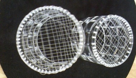
The first unconventional of the build is the drum triggers. The triggers are piezo elements folded up or cut down to fit inside highlighter bodies. These piezo/highliter/drum triggers were filled with melted candle wax to make sure the piezo doesn’t rattle around. [Rob] seems to have taken an empirical approach to cutting up piezo elements – smaller elements are less responsive, so they’ll be used for the zones of the drum head.

[Rob]’s drum heads are made from tennis and badminton raquets. The implementation is actually kind of clever: [Rob] restrings the raquets on the bias to vary the feel and responsiveness of the head. Check out the Flickr photoset of the build here.

The ultimate goal of [Rob]’s build is a “glass” drum set certainly inspired by [John Bonham]’s Vistalites. Whenever [Rob] puts up a video playing Moby Dick on his new kit, we’ll be sure to put it up.

Halloween Hacks: Motion Sensing Fog Machine

Halloween Hacks Banner

motion-sensing-fogger

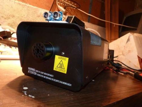
[monkeysinacan] wanted to add a fog machine to his Halloween display, but he says that the cheaper consumer-grade models are pretty unruly beasts. He cites short duty cycles and tricky fog control as his two biggest gripes with these sorts of foggers. He decided make the fogging process a little more manageable, and modified his to only generate fog when someone was walking nearby.

One obvious concern with this sort of setup is the warm-up time required to get the device ready to produce fog. If it were to only turn on when someone walked by, [monkeysinacan] would miss his mark each and every time. To ensure that his machine was accurate, he rigged it so that the heat exchanger stayed powered on, triggering the fog juice pump as needed.

To do this, he used an ultrasonic sensor similar to, but cheaper than a Parallax Ping unit. Paired with an Arduino, the sensor triggers the fog machine’s pump for 20 seconds whenever anyone gets within 6 feet of it.

While he hasn’t posted video of the modified fogger at work, it sounds like a solid plan to us.

Shutter Trigger Remote With Some Nice Design Considerations

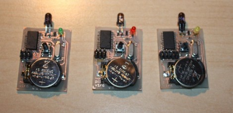
Here are the guts of [Lukasz’s] infrared camera remote control. He based it off of an existing design, but looked for places where improvements could be made. He felt the ATtiny2313 was a bit wasteful in this case. But further investigation led him to see why it was chosen. If you were to drop down to an ATtiny13 the ability to connect a crystal oscillator is lost (that chip only offers a 1-pin clock signal input) and the internal RC oscillator isn’t quite up to his standards for reliable IR communications.

Instead of driving the IR LED directly from an AVR pin he used a transistor in hopes that it will allow the maximum current to flow through the diode when in use. We’re not sure if it’s necessary, but we can see how it makes sense. Power is received from an unregulated 3 volt coin cell, so maybe as that voltage drops over time this will come into play.

Speaking of that coin cell, battery life is a concern here. [Lukasz] is using the sleep functions of the AVR after three seconds of use. This should keep the cell alive for quite a long time. But his 0 volt measurement is an anomaly with the multimeter he’s using. To get a precise measurement for tiny current flow you need extra equipment, like [Dave Jones’] uCurrent adapter.

The schematic for this Canon camera compatible project is only provided in Eagle format so we’ve embedded an image of it after the break for your convenience. You should have no problem making this work with a Nikon if you swap out some of the code from the TV-B-Gone shutter release we saw on Thursday.

Continue reading “Shutter Trigger Remote With Some Nice Design Considerations” →

Camping Light Retrofitted As A Solar Recharging Station

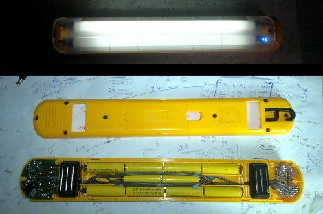
With grand plans of tenting out for several days at a music festival [Josh] needed a way recharge his portable devices. In the past he’s lugged around a 12V battery with him, but this year he wanted to make things easier. He ended retrofitting a camping light to do the job with the help of the summer sun.

The first step of the project was to source some rechargeable batteries. He toyed with the idea of Li-Ion cells but ended up going with NiMH because the charging is more forgiving and he got them at a great price. Because of the lower operating voltage (1.2V versus Alkaline’s 1.5V) he needed to squeeze two more into the lamp housing. Here you can see that he just managed to get them to fit in the wire-run area down the middle of the case.

Next comes the recharging circuit. He based his design around an ATmega44, using a voltage divider and the ADC to detect when the batteries are topped off. During the day this is connected to an external solar panel and it’s ready to charge his phone when he gets back at night.