In what is now a three-year long search, I’ve finally found the perfect use for an old cellphone. And with it, the answer to a burning question: Why aren’t we hacking cellphones?
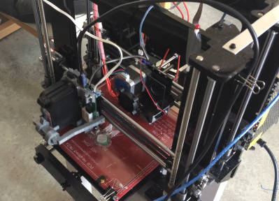
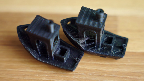
First, the application. The Octo4a project lets you use an old Android phone as a 3D printer server, web interface, and even time-lapse camera to make those nice movies where the print seems to grow up out of nothing before your eyes. It’s the perfect application for an old phone, making use of the memory, WiFi, graphics capabilities, and even the touch-screen if you want local control of your prints.
Connecting to the phone was the main hurdle that I’ve always seen in developing for cellphone projects, because I have robotics applications in mind. But Octo4a gets around this with low or no effort. Most 3D printers are designed to run on USB anyway, so connecting it to the phone is as simple as buying a USB OTG cable. With the USB port taken over, powering the phone long-run becomes a tiny problem, which can be solved with a Y-cable or a little solder. Keep the OS from going to sleep, somehow, and it’s problem solved!
But here’s why this isn’t a solution, and it points out the deeper problem with cellphone hacking that many pointed out in the comments three years ago. Octoprint is written in Python, and because of this is very easy to write extensions for and to hack on, if that’s your thing. When I first saw Octo4a, I thought “oh great, a working Android Python port”. Then I went to dig into the code.
Octo4a is written in Kotlin and uses the Gradle framework. It’s a complete port of Octoprint, not just to a different platform, but to a different programming language and to an almost entirely different programming paradigm. My hat is off to [feelfreelinux] for doing it, but my guess is that the community of other people fluent enough in Kotlin and Python to help port across upstream changes in Octoprint is a lot smaller than the community of Python programmers would have been. Octo4a is a great project, but it’s not a walk in the park to develop on it.
So all of you who wrote in the comments to my previous piece that it’s the Android software ecosystem that’s preventing phone reuse, well here’s the exception that proves your rule! A dedicated and talented, multi-lingual developer community could pull it off, but the hurdle is so high that few will rise to it.
Anyway, thanks [Feelfree Filip] for your great work! I’ll be putting this on my old S4.