Skip The Radio With This Software-Defined Ultrasound Data Link

We know what you’re thinking: with so many wireless modules available for just pennies, trying to create a physical data link using ultrasonic transducers like [Damian Bonicatto] did for a short-range, low-bitrate remote monitoring setup seems like a waste of time. And granted, there are a ton of simple RF protocols you can just throw at a job like this. Something like this could be done and dusted for a couple of bucks, right?

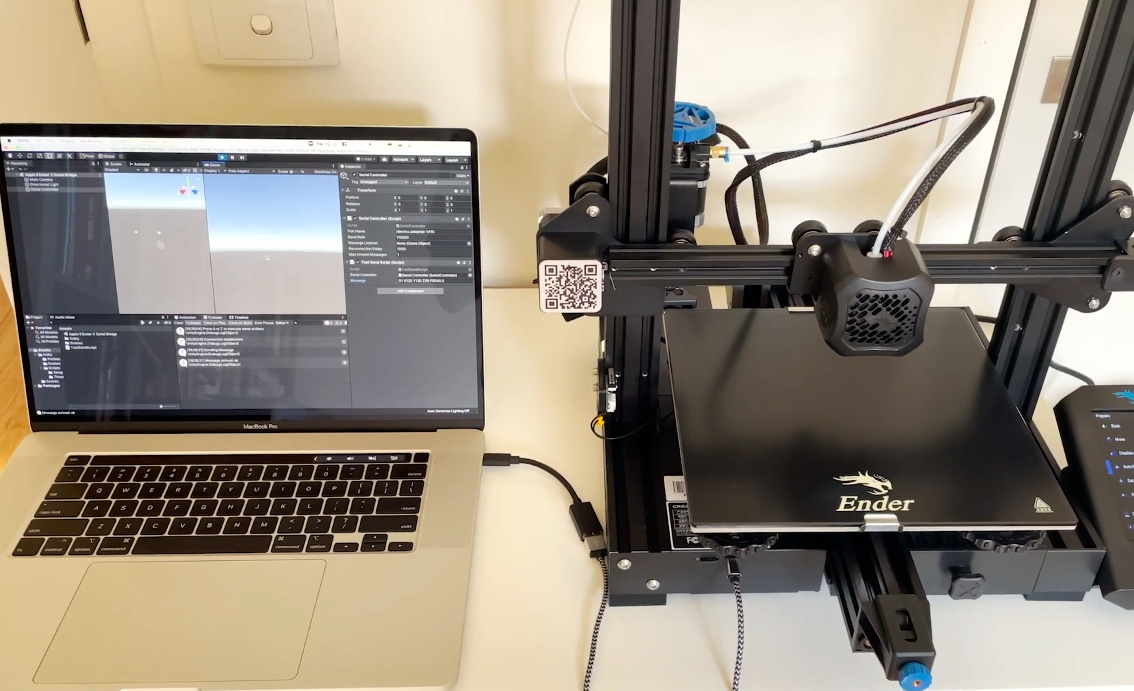
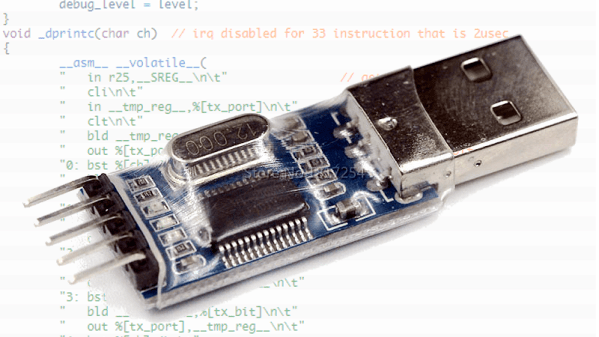
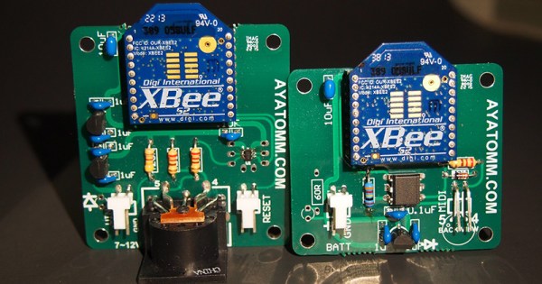
Luckily, [Damian] wanted something a little different for his wireless link to a small off-grid solar array, which is why he started playing with ultrasound in an SDR framework. The design for his “Software-Defined Ultrasonics” system, detailed in Part 1, has a pair of links, each with two ultrasonic transducers, one for receiving and one for transmitting. Both connect to audio amplifiers with bandpass filters; the received signal is digitized by the ADC built into an Arduino Nano, while the transmitted signal is converted to analog by an outboard DAC.

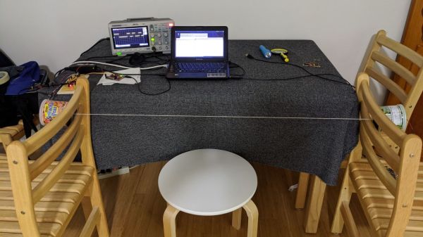
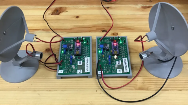
The transducers are affixed to 3D printed parabolic reflectors, which are aimed at each other over a path length of about 150′ (46 m). Part 2 of the series details the firmware needed to make all this work. A lot of the firmware design is dictated by the constraints introduced by using Arduinos and the 40-kHz ultrasonic carrier, meaning that the link can only do about 250 baud. That may sound slow, but it’s more than enough for [Damian]’s application.

Perhaps most importantly, this is one of those times where going slower helps you to go faster; pretty much everything about the firmware on this system applies to SDRs, so if you can grok one, the other should be a breeze. But if you still need a little help minding your Is and Qs, check out [Jenny]’s SDR primer.

Apple II Talks To 3D Printer With A Little Modern Help

Controlling most desktop 3D printers is as easy as sending them G-code commands over a serial connection. As you might expect, it takes a relatively quick machine to fire off the commands fast enough for a good-quality print. But what if you weren’t so picky? If speed isn’t a concern, what’s the practical limit on the type of computer you could use?

In an effort to answer that question, [Max Piantoni] set out to control his Ender 3 printer with an authentic Apple IIc. Things were made a bit easier by the fact that he really only wanted to use the printer as a 2D plotter, so he could ignore the third dimension in his code. All he needed to do was come up with a BASIC program that let him create some simple geometric artwork on the Apple and convert it into commands that could be sent out over the computer’s serial port.

Unity controlling the Ender 3

Unfortunately, [Max] ran into something of a language barrier. While the Apple had no problem generating G-code the Ender’s controller would understand, both devices couldn’t agree on a data rate that worked for both of them. The 3D printer likes to zip along at 115,200 baud, while the Apple was plodding ahead at 300. Clearly, something would have to stand in as an interpreter.

The solution [Max] came up with certainly wouldn’t be our first choice, but there’s something to be said for working with what you know. He quickly whipped up a program in Unity on his Macbook that would accept incoming commands from the Apple II at 300 baud, build up a healthy buffer, and then send them off to the Ender 3. As you can see in the video after the break, this Mac-in-the-middle approach got these unlikely friends talking at last.

We’re reminded of a project from a few years back that aimed to build a fully functional 3D printer with 1980s technology. It was to be controlled by a Commodore PET from the 1980s, which also struggled to communicate quickly enough with the printer’s electronics. Bringing a modern laptop into the mix is probably cheating a bit, but at least it shows the concept is sound.

Continue reading “Apple II Talks To 3D Printer With A Little Modern Help”

A Tin Can Modem, Just For Fun

Anyone old enough to fondly recall the “bleep-burp-rattle” sequence of sounds of a modem negotiating a connection over a phone line probably also remembers the simple “tin-can telephone” experiment, where a taut string transmits sound vibrations from the bottom of one tin can to another.  This tin can modem experiment puts both of those experiences together in a single project.

As [Mike Kohn] notes, this project was harder than it would seem that it should be. He actually had a much harder time getting the tin can phone part of the project optimized than getting the electronics sorted out, resulting in multiple tries with everything from the canonical tin cans to paper coffee cups before eventually settling on a pair of cardboard nut cans, the kinds with the metal bottoms. Linked together with a length of kite string — dental floss didn’t work — [Mike] added a transmitter on one end and a receiver on the other.

The transmitter used an ATtiny 2313 and everyone’s favorite audio amplifier, the LM386, while the receiver sported an electret mike preamp board, an LM566 tone decoder, and an MSP430 microcontroller. The modulation scheme was as simple as possible — a 400 Hz tone whose length varies whether it’s a one or a zero, or a stop or start bit. Connected to a pair of terminal programs, [Mike] was able to send his name over the wire string at what he calculates to be six or seven baud.

This project has all the hallmarks of lockdown boredom, but we don’t care because it’s good fun and a great learning opportunity, particularly for the young ones. There’s plenty of room for optimization, too — maybe it could even get fast enough for the Hackaday Retro 300-baud challenge.

Continue reading “A Tin Can Modem, Just For Fun”

Debugging With Serial Print At 5333333 Baud

Debugging with printf is something [StorePeter] has always found super handy, and as a result he’s always been interested in tweaking the process for improvements. This kind of debugging usually has microcontrollers sending messages over a serial port, but in embedded development there isn’t always a hardware UART, or it might already be in use. His preferred method of avoiding those problems is to use a USB to Serial adapter and bit-bang the serial on the microcontroller side. It was during this process that it occurred to [StorePeter] that there was a lot of streamlining he could be doing, and thanks to serial terminal programs that support arbitrary baud rates, he’s reliably sending debug messages over serial at 5.3 Mbit/sec, or 5333333 Baud. His code is available for download from his site, and works perfectly in the Arduino IDE.

The whole thing consists of some simple, easily ported code to implement a bare minimum bit-banged serial communication. This is output only, no feedback, and timing consists of just sending bits as quickly as the CPU can handle, leaving it up to the USB Serial adapter and rest of the world to handle whatever that speed turns out to be. On a 16 MHz AVR, transmitting one bit can be done in three instructions, which comes out to about 5333333 baud or roughly 5.3 Mbit/sec. Set a terminal program to 5333333 baud, and you can get a “Hello world” in about 20 microseconds compared to 1 millisecond at 115200 baud.

He’s got additional tips on using serial print debugging as a process, and he’s done a followup where he stress-tests the reliability of a 5.3 MBit/sec serial stream from an ATMega2560 at 16 MHz in his 3D printer, and found no missed packets. That certainly covers using printf as a debugger, so how about a method of using the debugger as printf?

Transmitting MIDI Signals With XBEE

What do you do when you want to rock out on your keytar without the constraints of cables and wires? You make your own wireless keytar of course! In order to get the job done, [kr1st0f] built a logic translator circuit. This allows him to transmit MIDI signals directly from a MIDI keyboard to a remote system using XBEE.

[kr1st0f] started with a MIDI keyboard that had the old style MIDI interface with a 5 pin DIN connector. Many new keyboards only have a USB interface, and that would have complicated things. The main circuit uses an optoisolator and a logic converter to get the job done. The MIDI signals are converted from the standard 5V logic to 3.3V in order to work with the XBEE.

The XBEE itself also needed to be configured in order for this circuit to work properly. MIDI signals operate at a rate of 31,250 bits per second. The XBEE, on the other hand, works by default at 9,600 bps. [kr1st0f] first had to reconfigure the XBEE to run at the MIDI bit rate. He did this by connecting to the XBEE over a Serial interface and using a series of AT commands. He also had to configure proper ID numbers into the XBEE modules. When all is said and done, his new transmitter circuit can transmit the MIDI signals wirelessly to a receiver circuit which is hooked up to a computer.

Hackaday Retro Edition: Hackadaying At 300 Baud

SONY DSC

For a bottom of the barrel website like our retro edition, there’s little reason to have a fast Internet connection. Even the fastest hands in the land can barely type faster than 300 baud. The problem with low-speed connections is the overhead involved, as [Pierre] discovered when he dug out an acoustic modem from the ’80s and loaded up our retro site.

While this isn’t the first modem ever made – that’s 1960s tech – but it does operate at the same speed – 300 bits per second, or slower than you reading this sentence. [Pierre] stuck a desk phone into the modem’s cups, plugged it in to a phone line simulator, and connected to a Raspberry Pi equipped with another modem. From there, it was pretty easy to set up a terminal at 300 baud.

A serial connection isn’t a connection to the Internet, however, and at 300 baud, PPP is nearly impossible. The overhead of encapsulating packets is just that high. SLIP is a much better choice to send IP packets over a slow serial connection, but [Pierre]’s mac doesn’t include the proper tools.

[Pierre] ended up using the serial connection between his Mac and Raspi with Zterm. From there, Lynx and Bob’s your uncle.

There’s an unsurprisingly long video of [Pierre] loading up the retro site below, as well an unsurprisingly long video of speedtest.net running at 56k.

Continue reading “Hackaday Retro Edition: Hackadaying At 300 Baud”

Optiboot Makes Your Arduino Faster, Sleeker

Tired of waiting for that Arduino sketch to upload? Find yourself limited by code space? Optiboot eases both of these problems. The package is an alternative bootloader that runs at a higher baud rate (115200 versus 57600) and it takes up 1.5 KB less space than the stock version. This means your sketches can be larger without upgrading to a beefier chip and they will take less time to upload, a lot less.

This fully compatible alternative to the Arduino bootloader requires an AVR ISP programmer to burn it to the chip on your Arduino. If you have an extra AVR lying around you could use the Arduino as a programmer and then physically swap the chips.

[Thanks Peter]