From the very first RepRaps to the newest and latest printers off the Makerbot assembly line, nearly every consumer 3D printer has one significant shortcoming: it cannot recover from missed steps, slipped belts, or overheating stepper drivers. Although these are fairly rare problems, it does happen and is purely a product of the closed open-loop control system used in 3D printer firmware.
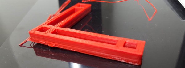
[Chris Barr] has come up with a rather clever solution to this problem. He’s designed a system that will detect and correct problems with the mechanics of 3D printers. It’s technically not a closed-loop control system, but it does allow him to get the absolute position of a nozzle on the build plate, detects error states, and can automatically calculate the number of motor steps per millimeter. It’s also much simpler than other closed loop control systems we’ve seen in the past, requiring only a few bits and bobs attached to the axes and to the printer controller board.
[Chris]’ system uses a magnetic encoding strip, a single chip, and a little bit of support circuitry. It’s actually not that much different from the moving axis on a desktop inkjet printer. It’s not closed loop, though; the firmware hack is only a ‘basic error correction’ that moves the nozzle back to where it should be. Although this is somewhat of a kludge, it is much simpler than refactoring the entire printer firmware.
In the video below, [Chris] demonstrates his solution for error correcting the printer by jerking his axis around during a print. The nozzle miraculously returns to where it should be, producing a usable part.
When the RepRap project was founded in 2005, it promised something spectacular: a machine that could build copies of itself. RepRaps were supposed to be somewhere between a grey goo and a device that could lift billions of people out of poverty by giving them self-sufficiency and the tools to make their lives better.
While the RepRap project was hugely successful in creating an open source ecosystem around 3D printers, a decade of development hasn’t produced a machine that can truly build itself. Either way, it’s usually easier and cheaper to buy a 3D printer than to build your own.
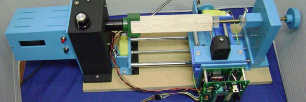
[castvee8]’s entry into the 2016 Hackaday Prize does just what the RepRap project promised ten years ago. It’s all about building machines with the ability to reproduce, creating an ecosystem of machines to build household goods. The best part? You can 3D print most of the machines. It’s the RepRap project, but for mills, lathes, microscopes, and routers. It’s an entire shop produced entirely in a 3D printer.
The idea of creating a machine shop from the most basic building materials has been around for a while. At the turn of the last century, concrete lathes and mills bootstrapped industrial economies. Decades later, [David J. Gingery] created a series of books on building a machine shop starting with a charcoal foundry. The idea of building a shop using scrap and the most minimal tools is very old, but this idea hasn’t been updated to the era where anyone can buy a 3D printer for a few hundred dollars.
So far, [castvee8] has a few homemade machine tools on the workbench, including a lathe, a tiny mill easily capable of fabricating a few circuit boards, and a little drill press. They’re all machines that can be used to make other useful items, and all allow anyone to create the devices they need.
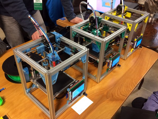
Only a few days ago, a significant proportion of the Hackaday crew was leaving Goshen, Indiana after the fourth annual Midwest RepRap Festival. We go to a lot of events every year, and even when you include DEF CON, security conferences, ham swap meets, and Maker Faires, MRRF is still one of the best. The event itself is an odd mix of people rallying under a banner of open source hardware and dorks dorking around with 3D printer. It’s very casual, but you’re guaranteed to learn something from the hundreds of attendees.
Hundreds of people made the trek out to Goshen this year, and a lot of them brought a 3D printer. Most of these printers aren’t the kind you can buy at a Home Depot or from Amazon. These are customized machines that push the envelope of what consumer 3D printing technology. If you want to know what 3D printing will be like in two or three years, you only need to come to MRRF. It’s an incubator of great ideas, and a peek at what the future of 3D printing holds.
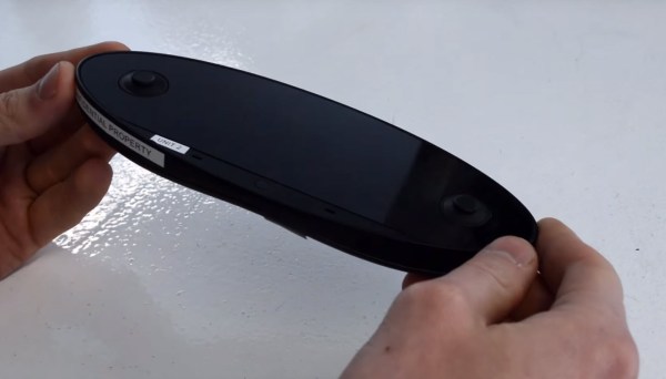
A few days ago you might have seen images floating around the net of the next Nintendo console controller, The Nintendo NX. There were so many pictures, it just had to be real!
Wrong. It was just [Frank Sandqvist] messing with everyone on the Internet. While phony product leaks are usually just photoshopped or 3D modeled renders, [Frank] took it a step further and actually designed a whole controller, 3D printed it, and took pictures of it. You might be wondering why he would do this. As a Reddit user points out there could be an excellent motive behind it:
You could also use it to get a job as a prop maker. It would look awesome on a CV that you made a prop that fooled the world — [Critters]
But, according to [Frank] it was really just for fun.
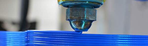
Alongside printers from all walks of manufacturing, one can naturally expect to find people selling different kinds of filament at a 3D printing festival. One of these purveyors of plastic was Proto-pasta out of Vancouver, WA. Proto-pasta prides themselves on unique offerings and complete transparency about their manufacturing processes.
Almost all of their filaments are either PLA or HTPLA with something special added during extrusion. The menu includes steel, iron, carbon, and finely ground coffee. The coffee filament was one of our favorites for sure. The print they brought with them looked solidified light roast and had a transparent kind of lollipop quality to it. I couldn’t detect the coffee scent due to allergies, but [Alex] assured me that printing with this filament will make your house or hackerspace smell terrific.
[Alex] was giving away samples of their stainless steel composite PLA. This one can be polished to a smooth shine with a series of papers that run from 400 to 8,000-grit. Another of their newer offerings is PLA infused with magnetic iron particles. Prints made with this stuff can be rusted to achieve an antique, steampunk, or shabby chic aesthetic.
Proto-pasta also has an electrically conductive composite carbon PLA. This one is great for capacitive applications like making a custom, ergonomic stylus or your own game controller. According to the site, the resistivity of printed parts is 30 ohms per centimeter as measured perpendicular to the layers, and 115 ohms along the layers.
Have you made anything awesome with conductive or magnetic filament? Have you had any problems with unorthodox filaments? Let us know in the comments.
What if we could reduce the cost of a photopolymer resin-based 3D printer by taking out the most expensive components — and replacing it with something we already have? A smartphone. That’s exactly what OLO hopes to do.
A resin-based 3D printer, at least on the mechanical side of things, is quite simple. It’s just a z-axis really. Which means if you can use the processing power and the high-resolution screen of your smart phone then you’ve just eliminated 90% of the costs involved with the manufacturing of a resin-based 3D printer. There are a ton of designs out there that use DLP projectors to do just this. (And there have been open-source designs since at least 2012.)
The question is, does it work with a cellphone’s relatively weak light source?
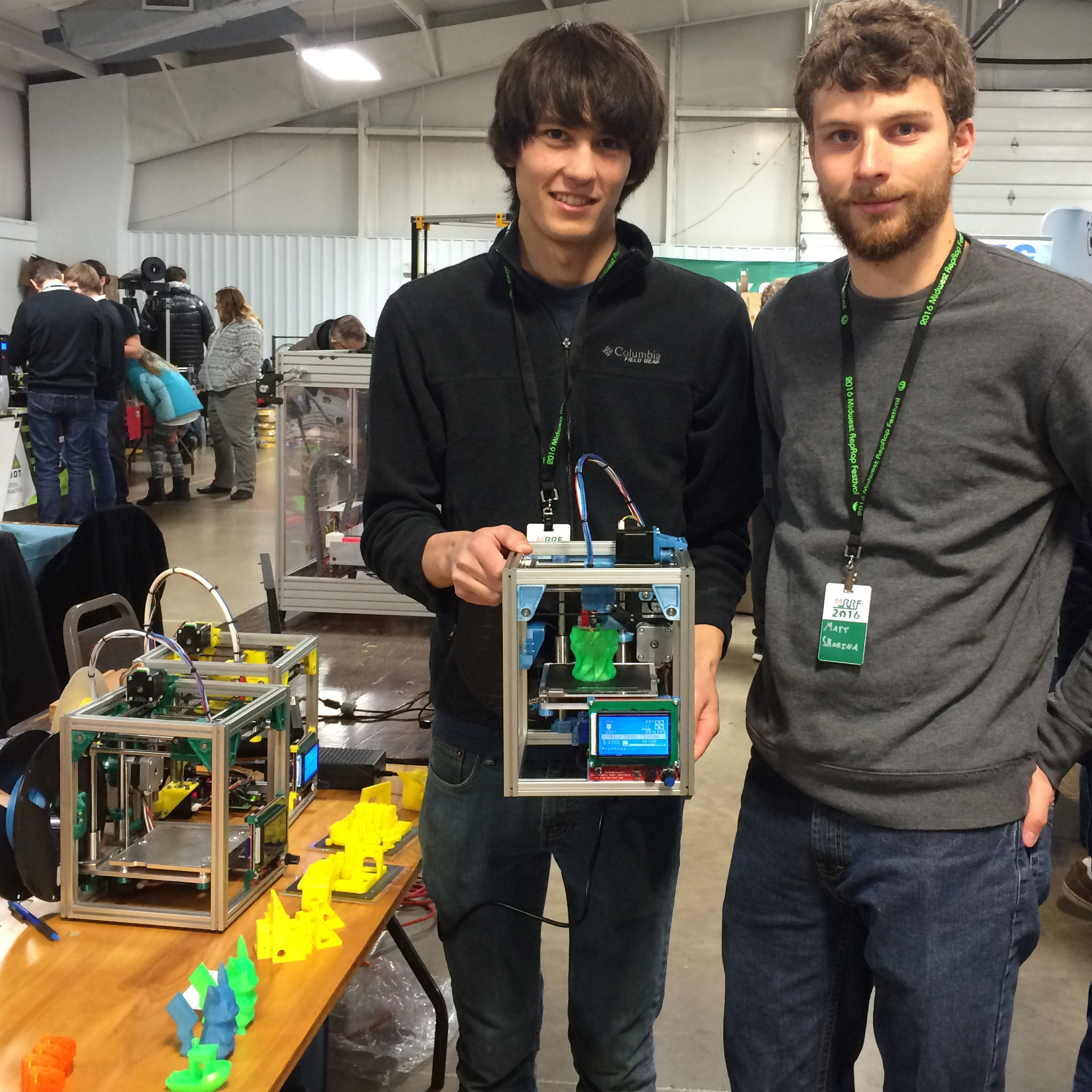
Patrick and Matt hold a running Kitten Printer. The frame is stiff enough that the printer can be held or turned upside down and it can keep printing without visible defects in the print.
[Patrick] and [Matt] have been coming to the Midwest RepRap Festival from Minneapolis for the past few years and bringing their trusty Tantillus printers with them. However, sometime between this year and the last [Patrick] decided that it would be really fun to make his own 3D printer, and liking the size and accuracy of the Tantillus, started there.
The adorably sized printer is adorably named too: Kitten 3D printer. The printer is certainly an enthusiast’s choice. It’s expensive at 1200 and small, but very well made. Its one big advantage? It prints really accurate parts.
The Tantillus also printed well, but the extruder left a lot to be desired, and the low stretch fishing line movement was very difficult to get tensioned just right. The secret behind the Tantillus and Kitten’s great print quality, aside from good design, is the small xy movement and low weight of the extruder set-ups. By having a movement over a very small range, cumulative errors in construction never get to add up. Also vibrations are less likely to show and smaller moments on the joints mean less flex at the extremes of the movements.
Really stunning print quality almost entirely free of ringing and z-wobble. 100mm x 100mm tray. These are very small parts.
[Patrick] is a mechanical engineer for his day job, and since this was a just for fun printer, he cut no corners. The frame is made with Misumi extrusions and linear movements. The build plate sits on a machined aluminum plate. It’s not flexing or going anywhere.
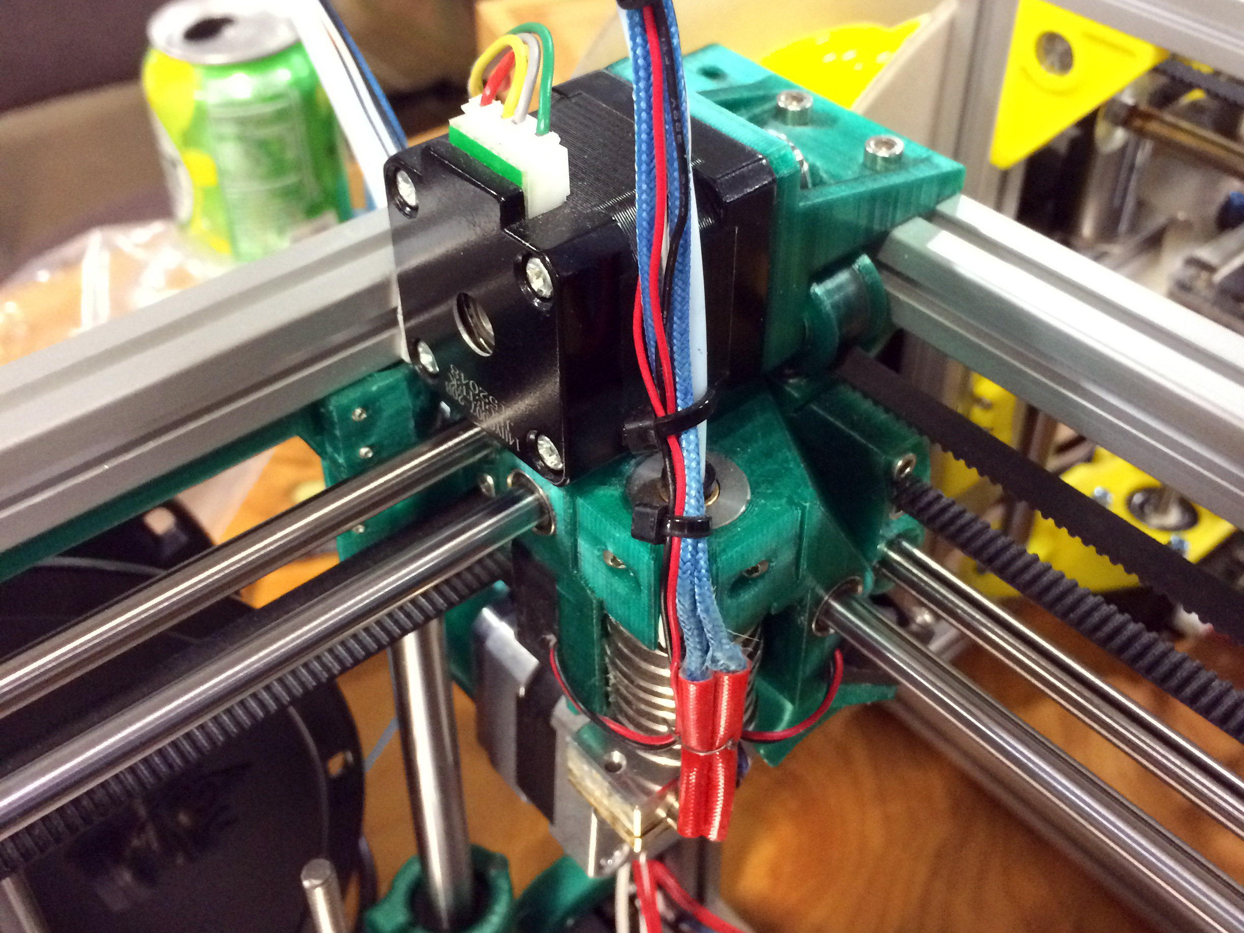
Part of what really stood out to me about the printer are a lot of neat little features which show careful thought. For example, the extruder movement sits neatly under one of the motors. All the parts except for one can be printed inside its build envelope without support. It uses around 200g of plastic. Every axis is constrained just enough, rather than the common tendency to over constrain that plagues 3D printer design. The spec sheet reads like my printer part wishlist: Bondtech extruder, Rambo board, E3d nozzle, heated bed, flat borosilicate build plate, name brand linear movements, and a well designed Z.
The entire extruder assembly tucks under one of the XY motors at the corner of its movement. Compare its size to the size of a NEMA14 stepper motor.
Another interesting aspect of the design is the extremely light extruder assembly. The lighter an extruder can get, the less ringing will show in your parts at speed. This is one of the most compact designs I’ve witnessed. It consists of two fans, an E3d v6 lite nozzle, and two small linear bearings. The cold end is handled by a bowden set-up and a Bondtech extruder at the back of the printer. The only way to get it lighter would be a different nozzle, such as the upcoming insanely light 13g Pico from B3 unveiled at the festival. I was also interested to see that the bearings on the supporting rails were printed bushings to keep the weight even lower. [nop head] has tested these extensively, they should be fine as long as the rods have a good finish.
I’ve mentioned the size before, but it’s hard to grasp just how adorable this printer is without seeing it. The build envelope is 100mm x 100mm x 100mm, the printer itself is 200mm x 200mm x 240mm. That’s only 50mm wider than the build footprint. It’s a really fun design just to look at and see how they fit it all in there. There are lots of neat little tricks with belt routing and part design to get it all right.
For the enthusiast this would make a good small parts printer and travel printer. However, for me, it was neat to see people still setting out to try designing their own printer. In some ways the 3d printer movement has become crowded with Chinese knock-offs, and I was excited to see something new at the festival. It wasn’t the only new printer design there, but it stood out to me the most. I like the uncompromising nature of it, many people try to design for the lowest BOM and not the nicer print. There are still lots of low-hanging fruit in the 3d printer world and many of them are just getting the mechanics right.
PLA Bushing
Seriously serious Z.
[Patrick] and [Matt] came to the festival with their printer to see if people would like it. They didn’t have grand dreams of selling tons of printers and making millions. They were quite aware that their price point and the small size made it not for everyone. However, their table always had a small crowd. They just really like 3D printers, and that honesty resonated. They didn’t even have a website up at the start of the convention, but by the end they had gotten so many requests they had to oblige. They expect to have 3 kit options available by the end of April. If you’re interested there’s a mailing list sign up on their website. Let’s hope we see them at MRRF again next year with another cool design to look over.