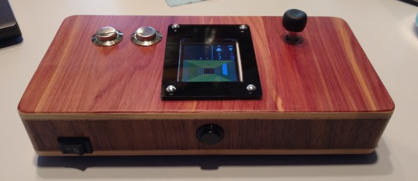
[Jason Carlson]’s favorite game as kid was 1983’s Treasure of Tarmin by Intellivision, a maze game that eventually came to be called Minotaur. As an adult there was only one thing he could do: remake it on a beautiful Arduino-based handheld.
[Jason] built the handheld out of a small-footprint Arduino Mega clone, a 1.8” LCD from Adafruit, a 5 V booster, a 1” speaker and vibe motor for haptic feedback. There are some nice touches, like the joystick with a custom Sugru top and a surprisingly elegant 2 x AA battery holder — harvested from a Yamaha guitar.
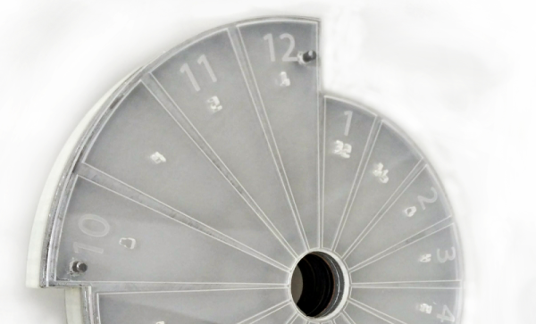
The maze maps are all the same as the original game, which [Jason] found online, but he stored the maps as bytes in an array to speed up the game—there was a flicker in the refresh already. However he added a progress map so players could see every area that was explored. In addition to Minotaur [Jason] also added remakes of Tetris, Simon and Snake, simpler games he wrote to test out the hardware.
We’ve published a bunch of handheld gaming projects over the years, including putting a Pi Zero in a GameBoy, building a throwback handheld, and playing Ocarina of Time on a N64 handheld.
Continue reading “Fight A Minotaur With This Gorgeous Handheld”