Simple To Build Programmable Foot Switches

programmable-footswitches

Your hands do a lot of work between the keyboard and the mouse, why the heck are you letting your feet be so lazy? [Dossier van D.] is putting an end to the podiatric sloth. He built this set of three foot pedals which have gone through two versions of functionality.

The buttons themselves are made from a base plate of plywood with a smaller piece on top for each ‘key’. The two parts are separated with some foam carpet pad, with a tactile push button in between to register a click. The only thing we’d change about this is adding a couple of wooden spacers next to the switch so that accidentally sanding on a button doesn’t break that electronic component.

Originally each button was soldered to a gaming controller. This worked just fine using button mapping, but recently [Dossier] made the switch to using an Arduino Leonardo. This is a perfect choice. Unlike input devices made with older Arduino versions the Leonardo board can natively register as a keyboard, making it a snap to programmatically map any key to the switches.

If you like this project you should check out [Dossier’s] foot mouse as well.

Python Frontend Is A GUI For Different Microcontrollers

python-frontend-gui-for-microcontrollers

[Navin] has been hard at work producing a GUI which works with different micocontrollers. The idea is to make it even easier to develop projects by simplifying the feedback and control you can get from the prototyping hardware. The best part about it is that he designed the software to interface with any hardware which can be programmed in C++.

The screenshot above shows the program communicating with an mbed board which has an ARM microcontroller. But the Arduino board (which uses an ATmega chip) is supported as well. Support for additional architectures can be added by writing your own configuration file for the chip. The Python program then asks for the com port it should be using for this session.

The source package, including the code which runs on the microcontrollers, can be found at the project repository. The functions used in the sketches are quite simple and should be a snap to drop into your own code projects.

Critter Cam Hacked From An Old Cellphone.

critter-cam-hacked-from-old-cellphone

[Art Barrios] kept having night-time visitors who were raiding his dog’s food storage bin. It’s a plastic tub with a lid that latches but the critters were knocking it over and popping that lid off. He wanted to find out which animal was the culprit so he hacked together an automatic camera system using an old cellphone.

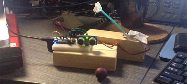
You can see the majority of the hardware he used in the image above. There’s an Arduino on the left. This monitors a switch which he added to the lid of the food storage container. It triggers the system when opened, switching on an LED light and snapping pictures.

The touchscreen button is used to trigger the shutter. That’s what all of that tin foil is about. Some experiments led [Art] to realize that a metal ‘finger’ could register on the screen if there was enough foil attached. To move the metal bracket he uses a solenoid. The last problem he faced was keeping the cellphone screen awake. He figured out that power cycling the charger does the trick. The Arduino manages this using a mains-rated relay.

The system successfully captured images of a family of raccoons feasting on the tasty morsels.

Using A Flashing LCD Monitor To Transfer Data

lcd-screen-data-transferWe love the concept of using an LCD screen to transfer data. The most wide-spread and successful method we know of is the combination of a QR code and the camera on a smart phone. But for less powerful/costly devices data can be transferred simply by flashing colors on the screen. That’s what [Connor Taylor] is testing out with this project. He’s using a TEMT6000 light sensor to turn a white and black flashing monitor into binary data.

So far this is just a proof of concept that takes measurements from the light sensor which is held in front of a Macbook Retina display with different backlight levels. At 3/4 and full brightness it provides more than enough contrast to reliably differentiate between black and white when measuring the sensor with the Arduino’s ADC. What he hasn’t gotten into yet is the timing necessary to actually transfer data. The issue arises when you need to have multiple 1’s or 0’s in a row. We’ve tried this ourselves using an LDR with limited success. We know it’s possible to get it working since we’ve seen projects like this clock which can only be programmed with a flashing screen.

[Connor’s] choice of the TEMT6000 should prove to be a lot more sensitive than using just an LDR. We figure he could find a way to encode using multiple colors in order to speed up the data transfer.

Arduinofied QRP Radio Beacon

moxpd

A while back, [m0xpd] picked up an unbearably cheap AD9850 DDS module from ebay. He turned this in to a Raspberry Pi-powered radio beacon, but like so many builds that grace our pages, the trolls didn’t like using such an overpowered computer for such a simple device. To keep those trolls quiet, [m0xpd] is back again, this time using the AD9850 DDS module as a radio beacon with an Arduino.

The previous incarnation of this build used a Raspberry Pi, and as a consequence needed a level converter. This was thrown out as [m0xpd]’s own Arduino clone, the WOTDUINO – pronounced, ‘what do I know’ – is able to handle the 5 Volt IO of the AD9850.

In addition to fabbing a shield for the DDS module, [m0xpd] also constructed a transmitter shield to amplify the signal and allow the ‘duino to key out a few simple messages. It’s a quite capable device – one of [m0xpd]’s messages traveled from merry olde England to Arizona, his best ever westward distance.

Reading Sensors With Scratch

Scratch, a graphical programming language developed by MIT’s Media Lab, is an excellent tool for teaching programming. [Daniel] created an Arduino Sensor Shield to interface with Scratch, allowing for real-world input to the language.

This board is a derivative of the Picoboard, which is designed for use with Scratch. Fortunately, the communication protocol was well documented, and [Daniel] used the same protocol to talk to the graphical programming environment. The shield includes resistance sensing, a light sensor, a sound sensor, and a sliding potentiometer.

The main goal was to create a board that could easily be built by DIY etching. This meant a one sided board with as few jumpers as possible. The final design, which can be downloaded and etched at home, is single sided and uses only one jumper. Detailed steps on testing the board are provided, which is very helpful for anyone trying to build their own.

This board is perfect for educational purposes, and thanks to [Daniel]’s optimizations, it can be built and tested at at home.

Arduino-controlled MIDI Sequencer

am808vx3-arduino-synth

[Christian] wrote in to tell us about his third-generation Arduino MIDI sequencer (translated) called the AM808 VX3. He had already laid a strong base for the project in his previous versions. But the user interface was still frustrating at times and that’s where this version comes in. it features a nice clean dashboard like interface, but also includes a configurable virtual interface.

The obvious components seen above include the slider and potentiometer band, as well as the repository of buttons mounted below that. But in the center of the board is a touchpad which [Christian] pulled out of an old Laptop. It interfaces as a PS2 device which makes it pretty simple to use in conjunction with the Arduino. But that’s not the only touch-enabled input device. The rectangle to the right of the touch pad is an LCD screen with a touch overlay. As you can see (and hear) in the clip after the break, the touch screen made it possible for him to rework the controls until they became simple and intuitive.

Continue reading “Arduino-controlled MIDI Sequencer”