Cutting Paper Scrolls With Frickin’ Lasers

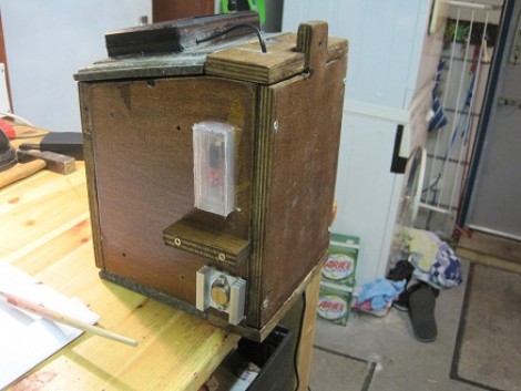
This circuit illustration adds a scrolling paper feeder to the bed of a laser cutter. In the video after the break you can see that the actual assembly is put on the bed of the laser cutter. After the laser has cut out the specified pattern, the scroll is wound to move an un-cut portion into place. It uses a servo motor to drive one of the spools.

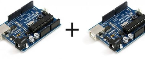
An Arduino Uno with a servo shield is being used for this application. It has one button which winds one spool for a pre-programmed period of time. There’s a few issues with this setup, namely that it’s not tied into the CNC program that runs the laser. There’s also a lack of precision when using a continuously rotating servo like this. If it were upgraded to use a stepper motor and patched into the CNC hardware this would make cutting new scrolls for your player piano a breeze.

Here’s a project that does the opposite, it takes old player piano rolls and digitizes them.

Continue reading “Cutting Paper Scrolls With Frickin’ Lasers”

Real-time Robotic Arm Control With Blender

robotic_arm

Last year, [Justin Dailey] was coming down the home stretch of his senior year as a Computer Engineering student and needed to build a final design project. He always wanted to construct a robotic arm, and figured that there was no better way to legitimize such a project, than to claim that it was “homework”.

While he originally wanted to control the arm with a joystick, he had been messing with Blender quite a bit leading up to his final project, and thought it would be pretty cool to let Blender do the work. He started out by testing his ability to control a single servo with Blender, then slowly increased the complexity of the project. He prototyped the arm using cardboard, and satisfied with his progress thus far, began constructing the arm out of aluminum.

Once he had all six of his servos attached to the arm’s joints and wired to his Roboduino, he got busy constructing a 3D model in Blender. Using a few Python scripts, the movements inside Blender are translated to serial data in real-time, which is relayed to the Roboduino in order to control the arm.

Check out his site if you get a chance – there’s plenty of code to be had, as well as several videos of the arm in various stages of construction and testing.

Large Remote-controlled Game Of Life Display

game_of_life

Sometimes it’s just plain fun to over-engineer. [Stephanie] gets a warm fuzzy feeling when she successfully adds way more electronics components to a project than she really needs – just because she can. We can’t really argue with her if that is the intended goal, nor can we find fault with the sweet Game of Life display she put together.

She started off with six Game of Life kits from Adafruit, but she quickly caught the LED bug and her collection grew until she had 20 kits (that’s 320 LEDs for those of you keeping count). After piecing them all together, they were mounted in a wooden frame and placed behind a dark piece of acrylic. It looked great and worked just fine, but it wasn’t overdone enough for her tastes.

In the end, she added a small Arduino and Xbee module to the Game of Life display, which enables it to be controlled by her network-enabled thermostat we featured a few weeks back. The thermostat was fitted with an Xbee unit as well, which allows it to turn the Game of Life on and off at whatever times [Stephanie] specifies.

We’ll take two please.

[via Adafruit Blog]

rc_car

Racing Wheel Guided R/C Car With Video Feed

Instructables user [Kaeru no Ojisan] enjoys constructing R/C kit cars and wanted to build one that could be driven using a PC racing wheel he had on hand. Not satisfied with simply guiding it with the racing wheel, he added a web cam to the car so that he can monitor its location from the comfort of his desk chair.

The car is loaded down with all sorts of electronics to get the job done, requiring four separate battery packs to keep them online. An Arduino controls the motor and the steering servos, receiving its commands wirelessly via a Bluetooth add-on. The camera connects to a USB to Ethernet converter, which enables the car’s video feed to be transmitted via the onboard wireless router.

The racing wheel interface seems to work just fine, though we don’t doubt that the whole setup can be easily simplified, reducing both weight and battery count. While [Kaeru no Ojisan] says that the car is in its concept stages and there are a few bugs to work out, we think it’s a good start.

Stick around to see a quick video of the car in testing.

Continue reading “Racing Wheel Guided R/C Car With Video Feed”

Real-time Digital Puppetry

digital_puppet_show

If it sometimes seems that there is only a finite amount of things you can do with your kids, have you ever considered making movies? We don’t mean taking home videos – we’re talking about making actual movies where your kids can orchestrate the action and be the indirect stars of the show.

Maker [Friedrich Kirchner] has been working on an application called MovieSandbox, which is an open-source realtime animation tool. A couple of years in the making, the project is cross-platform compatible on both Windows and Apple computers (with Linux in the works), making it accessible to just about everyone.

His most recent example of the software’s power is a simple digital puppet show, which is sure to please young and old alike. Using sock puppets fitted with special flex sensors, he is able to control his on-screen cartoon characters by simply moving his puppets’ “mouths”. An Arduino is used to pass the sensor data to his software, while also allowing him to dynamically switch camera angles with a series of buttons.

Obviously something like this requires a bit of configuration in advance, but given a bit of time we imagine it would be pretty easy to set up a digital puppet stage that will keep your kids happily occupied for hours on end.

Continue reading to see a quick video of his sock puppet theater in action.

[via Make]

Continue reading “Real-time Digital Puppetry”

ChronoTune: Listen To Radio By Year, Not By Frequency

The ChronoTune is a radio that plays sounds from different eras. This project was developed as an entry for the Redbull Creation Challenge by some members of i3Detroit, a hackerspace in the motor city. It allows a user to turn the dial to tune in a new moment in history, but they can also listen in on the present day. They’ll be greeted with the sounds of a tuning radio, followed by music or audio clips common to the period displayed on the dial.

As you know from the last contest entry, each project must use an Arduino to qualify. It reads a rotary encoder attached to one of the knobs on the front of the case. This doesn’t directly move the tuning needle. Instead, it’s attached to the guts of an inkjet printer to move it back and forth. This lets the radio tune itself if need be.

The audio is played from several sources. There is an MP3 module that allows for longer clips, but there are also some ISD voice recorder chip modules that play back shorter clips. If the dial is tuned to present day, an FM radio module tunes in a station over the air.

Having trouble reading that dial? Don’t worry, there’s a simulated Nixie tube display sticking out the top of the case to provide a digital readout of the currently selected time period. Check out the video after the break to see the team walk us through each part of the ChronoTune.

Continue reading “ChronoTune: Listen To Radio By Year, Not By Frequency”

BlinkM Smart Garage Door Opener

garage_indicator

Calling Canada home, Hackaday reader [TheRafMan] has seen his share of bitterly cold winters. He also knows all too well how hard it is to get his cars started in the morning if somebody happens to leave the garage open. After the door was left open overnight for the second time this last winter, he decided that it was time to add an indicator inside the house that would alert him when the garage had not been closed .

Inspired by our BlinkM Arduino coverage a short while back, his circuit incorporates a BlinkM as well as several other components he already had on hand. He disassembled the garage door switch situated in the house and fit the BlinkM into the switch box once he had finished programming it. A set of wires was run to the BlinkM, connecting it to both a power supply located in the garage as well as the magnetic switch he mounted on the door.

The end result is a simple and elegant indicator that leaves plenty of room for expansion. In the near future, he plans on adding an additional indicator strobe to let him know when the mail has arrived, not unlike this system we covered a few months ago.

Stick around to see a quick video demonstration of his garage door indicator in action.

Continue reading “BlinkM Smart Garage Door Opener”