The transistor may rule the electronics world today, but before solid state moved in, vacuum state was king. Tubes, or valves if you’re from Europe, were the only way to fly. Every good hacker knew their triodes from their tetrodes and their pentodes. While technology has moved on, some hackers keep the past alive with tube based projects. This week on the Hacklet, we’re featuring some of the best tube projects on Hackaday.io!
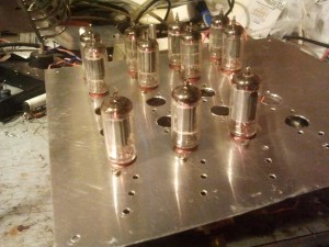 We start with [256byteram] and Tube Television Tennis. [256byteram] is building an entire Pong style game from tubes, including a CRT to display the game. Displaying anything on a standard television means generating lots of timing signals. [256byteram] is doing this by using multivibrators to create one-shots and flip-flop circuits. Tube Television Tennis is still a work in progress, but [256byteram] already can display a paddle and move it around the screen in both X and Y. This project has already blown our minds!
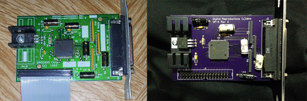
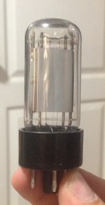
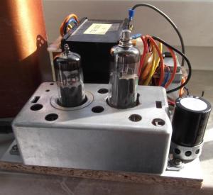 From [Marcel] comes this great Low Voltage All-Tube Amplifier, which we featured on the blog earlier this year. [Marcel] does tubes without the danger of high voltage by using the ECL82 tube at 40 volts. The ECL82 incorporates both a triode pentode in one package, making it something of an integrated circuit. Power is provided by transformer while a PY88 tube handles rectifier duties, making this truly an all tube amp. A few passive components complete the design. We can’t wait to fire one up and hear some class A goodness while basking in the warm glow only a tube can create.
 No tube article would be complete without some nixies, and [opeRaptor] is here to provide them with Obsolete Time, a nixie tube clock! Obsolete Time uses IN-12 Russian nixie tubes, and goes for a minimalist design. Under the hood it’s all modern tech though, including a Bluetooth radio which allows the clock to be set via an Android app.
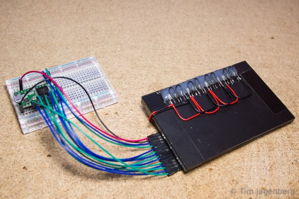
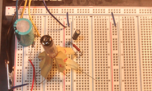 [Brandon Foltz] is also getting into a vacuum state of mind as he takes Adventures in Hybrid Headphone Amps. [Brandon] is mixing the best of the old and new worlds by using a 6247 tube as the input stage to an LM386 single chip amplifier. This hybrid is still a work in progress, as [Brandon] is trying to clean up the sound from his LM386.
Hackaday.io update!
 Did you know that we’re constantly upgrading Hackaday.io? We listen to your input on the feedback project, and we’re always adding new features to the site. If you haven’t noticed, you can now send private messages to other users. We’re sure this will help put users in contact with each other, so they can collaborate on even more projects! On the left side of each profile page there is a “Send a private message” button below the hacker’s avatar. You now have better indicators when you have messages or updates too! The private messages and feed icons at the top right of every .io page now have indicators to show how many messages or feed entries you have waiting. These are all based on live data, so they’ll update as you browse the site.
That’s all the time we have for this week’s Hacklet! As always, see you next week. Same hack time, same hack channel, bringing you the best of Hackaday.io!