This is a project that is about a year and a half in the making, but [Fran] is finally digging into the most iconic part of the Apollo Guidance Computer and building the most accurate reproduction DSKY ever.
The Apollo Guidance Computer was a masterpiece of engineering and is frequently cited as the beginning of the computer revolution, but it didn’t really look that interesting – it looks like a vastly overbuilt server blade, really. When everyone thinks about the Apollo Guidance Computer, they think about the DSKY, the glowey keypad interface seen in the blockbuster hit Apollo 13 and the oddly accurate disappointment of Apollo 18. It’s the part of the Apollo Guidance Computer the Apollo astronauts actually interacted with, and has become the icon of the strange, early digital computers developed for NASA in the 60s.
There are a few modern DSKY replicas, but all of them are exceedingly anachronistic; all of these reproductions use seven-segment LEDs, something that didn’t exist in the 1960s. A true reproduction DSKY would use custom electroluminescent displays. These EL segments are powered by AC, and transistors back then were terrible, leading to another design choice – those EL segments were turned on and off by relays. It’s all completely crazy, and aerospace equipment to boot.
Because of the custom design and engineering choices that seem insane to the modern eye, there isn’t much in the way of documentation when it comes to making a reproduction DSKY. This is where [Fran] tapped a few of the contacts her historical deconstruction cred earned when she reverse engineered a Saturn V Launch Vehicle Digital Computer to call upon anyone who would have access to a real Apollo-era DSKY.
The first contact was the Kansas Cosmosphere who was kind enough to send extremely detailed photographs of the DSKYs in their archives. It would have been extremely nice to have old documentation made when the DSKYs were rolling off the assembly line, but that information is locked away in a file cabinet owned by Raytheon.
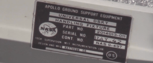
[Fran] got a break when she was contacted by curators at the National Air and Space Museum’s Garber facility who invited her down to DC. She was given the grand tour, including the most elusive aircraft in the museum’s collection, the Ho 229, the dual-turbojet Nazi flying wing. At the Garber facility, [Fran] received permission to take apart two DSKYs.
The main focus of [Fran]’s expedition to the Air and Space Museum was to figure out how the EL displays were constructed. The EL displays that exist today are completely transparent when turned off because of the development of transparent conductors.
The EL displays in the DSKY were based on earlier night lights manufactured by Sylvania. After looking at a few interesting items that included Gemini hardware and early DSKYs, this sort of construction was confirmed.
With a lot of pictures, a lot of measurements, a lot of CAD work, and some extremely tedious work, [Fran] was able to create the definitive reference for DSKY display elements. There are 154 separate switchable element in the display, all controlled by relays. These elements are not multiplexed; every element can be turned on and off individually.
Figuring out how the elements were put together was only one part of [Fran]’s research. Another goal was to figure out the electrical connections between the display and the rest of the DSKY. There, [Fran] found 160 gold pins in a custom socket. It’s bizarre, and more like a PGA socket than like the backplane connector [Fran] found in the Saturn V computer.
Even though [Fran]’s research was mostly on the EL panel inside the display, she did get a few more insights with her time with the DSKYs. The buttons are fantastic, and the best keys she’d ever used. This is just part one of what will be an incredibly involved project, and we’re looking forward to what [Fran] looks into next.

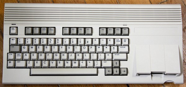
 The C65 is not a contemporary of the C64, or even our own [Bil Herd]’s C128. This was the Amiga era, and the C65 was intended to be the last great 8-bit machine.
  The Hackaday Retro Edition is our celebration of old computers doing something modern, in most cases loading