Building A New Motherboard For A TRS-80

Trash80

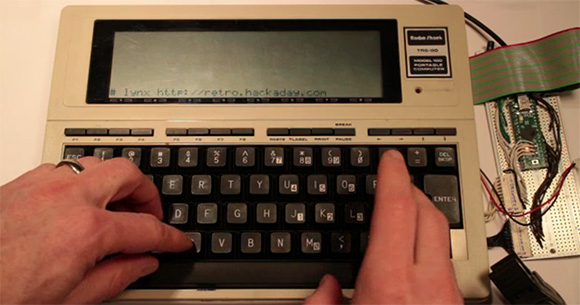
The TRS-80 Model 100 was an amazing piece of kit when it was released. Able to run for a week with just four AA batteries and smaller than some laptops today, this portable version of the TRS-80 saw action with war correspondents covering the Falklands invasion. A pedigree a MacBook Pro will never be able to live up to, it seems.

[Hudson] picked up a non-functioning Model 100 with the express goal of replacing the 30-year-old electronics inside with an updated motherboard – and also pull up our retro site in the process. Armed with a Teensy++, [Hudson] pried open his ancient computer and set to work interfacing the display and keyboard to his AVR dev board.

The LCD display in the Model 100 has a resolution of 240×64, driven by ten Hitachi HD44102 display drivers. Each of these display drivers are responsible for the pixels in a 50×32 rectangle on the screen and are interfaced with a 30-bit wide bus consisting of chip select lines, and 8-bit data bus, and a few other random control lines. [Hudson] plugged this 30 pin header into his Teensy++ and after a bit of ingenuity regarding the strange electrical requirements of the LCD, was able to control every pixel on this 30-year-old display.

The next order of business was interfacing the keyboard with a modern microcontroller. The keyboard is laid out in a normal matrix, but with a few oddities: characters like ~, |, and curly brackets aren’t present on the Model 100. After working these problems out, [Hudson] set to work on a VT100 terminal emulator. This allowed him to run vi and lynx, enabling him to pull up the Hackaday retro site in a wonderful forty-column text mode.

Future improvements to this redesign include designing a proper PCB to replace the current protoboard design. The original Model 100 included a text editor and programming language, and adding a Forth implementation isn’t out of [Hudson]’s grasp. It’s an awesome build, and an excellent improvement that will allow [Hudson]’s Trash-80 to see another 30 years of use.

Frankenstein, An All-tube Home Theater Amplifier

amp

Here’s an exercise in excess if we’ve ever seen one. While working on his undergrad at Michigan State, [Gregory] thought it would be a great idea to build an all-tube home theater system. He calls his seven-foot tall rack of amplifiers ‘Frankenstein,’ and we’ve got to agree this build is an impressive monstrosity of engineering prowess.

[Gregory]’s Frankenstein is a complete 5.1 home theater system. In the interests of sanity, the majority of the equipment in the rack is off-the-shelf gear including a CD player, surround sound processor, and a beautiful McIntosh solid state preamp. The power amps, though, are where this build really shines.

For the sub, [Gregory] built a wonderful monoblock tube amp, able to push nearly 300 watts into a subwoofer. The other channels for this home theater system are amplified with a huge four channel tube amp providing 480 watts per channel. In total, there are 23 tubes in [Gregory]’s amplifier system, enough to consume 20 amps of filament current.

You can check out [Gregory]’s demo video of his system after the break.

Continue reading “Frankenstein, An All-tube Home Theater Amplifier”

Fabricating Hardware From The Original Arcade Pong Schematics

original-arcade-pong-rebuild

This heavily populated PCB is a recreation of the original arcade version of Pong. That is an important distinction because the home version of Pong used a specialized chip to do much of the work. This is basically all stock logic, which explains the high component count. We wonder how many quarters it took just to pay for all 66 chips at the time?

[Pong74ls] was the person who took on this project. There is an original schematic available, but it’s incredibly crowded and rather difficult to figure out. Fortunately [Dan Boris] has already done a lot of the heavy work. He took the one-page nightmare and turned it into a sixteen page plan for building the original board (look for the schematic link under technical details).

Before the board could be laid out some redesign work was necessary. It sounds like some of the original chips are out of production and suitable replacements needed to be found. The board was then laid out in Eagle before sending the design off to a fab house. There was just one error which didn’t allow the ball to bounce when hitting a paddle while travelling downward. A couple of jumper wires fixed that right up!

[via Reddit]

[Original Reddit Post]

[Staci Elaan]’s Awesome Portable Tesla Coils.

We stumbled onto [Staci’s] videos a while ago when we posted this big tesla gun. While it wasn’t the first portable coil we had seen, it was certainly an impressive implementation. In the comments we found [Staci] had already been making these for a while. Hers were big and small, had awesome modulation, and looked freaking cool too.

It also should be pointed out that [Staci] donates her coils to people when she’s done! Let me say that again, she gives them away to groups of people that could use them. That deserves some respect.

Unfortunately, [Staci] didn’t document her builds in great detail at the time. She has added some information recently though.   You can read about her first working prototype from 2006, or a slightly more modern one here.

Of course, the real fun is in seeing them work.

Continue reading “[Staci Elaan]’s Awesome Portable Tesla Coils.”

An Introduction To Vector Displays

clock

Unlike the CRTs found in big old televisions, vector displays are a bit of a historical oddity. Instead of sweeping an electron beam across the screen from left to right and top to bottom, a vector display draws lines between two points on a screen. Once used in arcade games such as AsteroidsTempest, and old FAA displays, vector monitors have fallen out of favor due to either the complexity or difficulty in acquiring the needed CRT. The folks over at NYC Resistor put up a great tutorial for getting a vector display up and running, and even managed to put a clock on an oscilloscope.

The key component of getting a vector display to work is the digital to analog converter. This DAC takes voltages from eight pins on a Teensy 2.0 dev board and converts them to a voltage anywhere in between 0 and 5 Volts. After connecting the output of this DAC to an input on an oscilloscope, the microcontroller can draw a line between any two points on an axis.

In the video after the break, you can see two of these DACs connected to an oscilloscope displaying a clock. It’s a very cool piece of work, and something that finally gives a purpose to the ancient CRT oscilloscope you might have lying around.

Continue reading “An Introduction To Vector Displays”

Cute Little Amplifier Has A Tube Pre

tube

While you won’t catch us in an argument with an audiophile regarding the sound quality of tube vs. solid state amps, there is a general consensus that tube amplifiers sound much better than their transistorized brethren. Actually building an all-tube amplifier, though, is a bit harder than one built around common ICs – there are transformers to deal with and of course very high voltages. One solution to get the sound of tubes easily but still retaining the simplicity of integrated circuits is a hybrid amp, or a tube preamplifier combined with a solid state power section. They’re easy enough to build as [Danilo] shows us with his hybrid tube amp design (Italian, translation).

[Danilo]’s design uses two ECC86 for the left and right channels powered by a 12 Volt supply. Each channel is sent through a tube and then amplified by a TDA2005 20 Watt power amplifier. After plugging in a CD player, the result is a clear, warm sound that can put a whole lot of power through a speaker.

Teaching The Speak & Spell Four (and More) Letter Words

ss

Before it became the darling of circuit benders the world over, the Speak & Spell was a marvel of modern technology. Complete with a microprocessor and voice synthesizer, the Speak & Spell was able to speak a limited vocabulary that [Furrtek] thought should include words such as, “al qaeda”, “necrosis”, and “butt”. The Speak & Spell included an expansion port for cartridges containing a larger vocabulary, and with a huge amount of effort [Furrtek] created his own Speak & Spell carts that allow it to talk like a sailor.

The Speak & Spell ROMs were stored on a very strange memory chip; instead of a parallel or serial interface, the chip reads five nybbles at a time before returning the saved data. At first, [Furrtek] thought he could get an ATtiny microcontroller, but the way this memory chip is set up made it impossible to send and receive data even on a 400kHz I2C bus.

The project eventually found some decent hardware in the form of a CPLD-based cartridge that was more than fast enough to interface with the Speak & Spell. After that, it was only an issue of converting words into something the speech synth can understand with some old Windows 3.1 software and finally burning a ROM.

The end result is a Speak & Spell with a perverse vocabulary and is much, much more interesting than a circuit bent piece of hardware with a few wires crossed. Check out the video after the break.

Continue reading “Teaching The Speak & Spell Four (and More) Letter Words”