Reader [Jan] came across a website all about building your own video projector. We’ve linked to five of the best projects for 2010 but there’s a ton more information if you dig a little deeper. Our favorite so far is the GohtanBox v3 and it’s giant LED panel that serves as the projection light.
classic hacks2768 Articles
LED And Fan Controller
Needing a front fan to keep his hard drive cool, [CalcProgrammer1] found he was unhappy with a single LED color for the fan. He swapped them out for a set of four RGB LEDs and whipped up his own controller board for the unit. It is based around an ATmega168 and patches into the COM2 header on the motherboard, providing a serial interface. [CalcProgrammer1] wrote a GUI to control fan speed, and individual LED color settings. You can take a look at and enthralling, edge-of-your-seat demonstration of how slider controls work after the break. Wouldn’t it be great if the HDD LED clock could be adapted to use a fan so that the front panel had a colorful analog dial on it? Continue reading “LED And Fan Controller”
Automatic Telephone Recorder
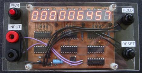
[James Bond] types and those suffering from a hefty dose of paranoia can now record all telephone conversations. [Trax] built this module that monitors the phone line and starts recording when a handset is picked up. A computer does the actual recording, triggered by the microcontroller via a USB connection.
We like the use of an old PCB for a faceplate, we’ve certainly got some duds of our own sitting around. The three cords are a bit confusing though. One for the phone line, one for the USB, but what does the third do? Is it an audio-out connection?
We’ve asked [Trax] to post a schematic and source code if possible so that might clear up the mystery.
Update: [Trax] let us know that there is a red button with white lettering at the bottom labeled “download”. This contains schematic, code, pcb layout, and PC software. We just missed it the first time around.
DoomBox: Classic Keys Meet Tiny Screen
The doomBox is a dedicated gaming rig for lovers of ID Software’s classic title. [JJ] built this from an old Kodak DC290 camera that had a broken lens. Since this runs the Digita OS, he was able to use the Doom port that already exists. But the camera’s factory buttons were not well suited as controls. By whipping up his own button board, and using the traditional keyboard keys for the button caps, he achieved a much more comfortable (yet squint-inducing) gaming experience. The finished project resides in an all-too-familiar black project box. See him fire it up after the break.
The original Doom for Digita OS pages seem to be down so here’s an alternate if you’re interested.
Update: Looks like the original website is back up.
Two Input Devices Made With Common Items
Here’s two input devices you can easily build with materials you already have on hand.
To the left, [John] built a 3×3 keypad matrix from paper and tinfoil. The rows and columns are made up of strips of tin foil on the front and back layers of paper. The layers are separated by spongy double-stick tape. A ‘keypress’ results when the gap between the conductors is compressed with your finger.
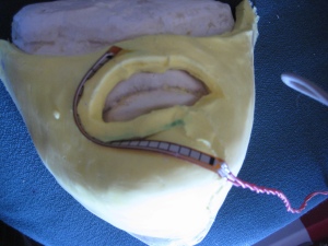
In much the same way, [Dave Fletcher] built a touch potentiometer. He made two resistance plates by scribbling pencil lead on sheets of paper. When the two plates face each other, separated by the same type of foam tape as before, they can be pressed together to form a circuit with a variable resistance. This results in a crude version of the SparkFun softpot.
Oscilloscope Doubles As A Serial Terminal
PC-based USB oscilloscopes are fast becoming all the rage. [Matt Sarnoff’s] Terminalscope takes the reverse approach, adapting an oscilloscope into a full serial terminal. You may have seen something similar before in the Dutchtronix/SparkFun O-Clock, but [Matt’s] project goes one further by adding a PS/2 keyboard port for full bidirectional serial communication, and with much sharper display resolution to boot.
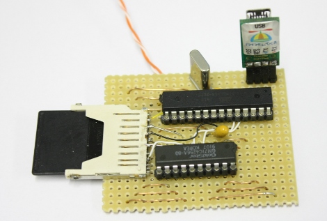
The mostly VT-100 compatible Terminalscope is built around two AVR microcontrollers: an ATmega328P runs full-tilt to generate the video signal and handle serial I/O, while an ATtiny45 handles keyboard input to avoid interrupting the ’328’s duties. Rather than vector trace each character, a raster-scanning approach is used: the beam follows a fixed X/Y path (like a television), while modulating the Z input (beam intensity) to form an image. The device can be connected to a PC via serial port or USB-to-TTY adapter, or directly to another microcontroller to debug serial output.
We recently showed an oscilloscope being used as a multichannel digital logic display. The Terminalscope provides yet another use for this essential bench tool and could nicely round out a “poor man’s” testing setup. The schematic and full source code are available for download.
Add Pause Button To The Atari 2600
We’re sure that if there had been a pause button on the Atari 2600 people would never have moved on to next-generation systems. Now you can dig the gaming relic out of the closet and pause your Atari games for some good old om nom nom.This hack is from the same person who pulled off the Atari 2600 jukebox. By reverse engineering the signals used on the Onyx Jr., which has a pause button, the halt method became clear.
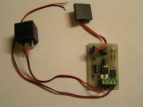
The problem is that the Onyx Jr. uses a different processor than the 2600. A different processor means a different pin-out, and now the clock signal needed to synchronize the pause cycle was missing. But eureka, an abstract source was found. The ready signal from another chip can be used to judge the state of the processor. The small PCB above now interfaces with the Atari 2600 in order to patch in the pause circuit.
[Thanks again Yuppicide, keep ’em coming!]