A Pick And Place Machine For Under $1k

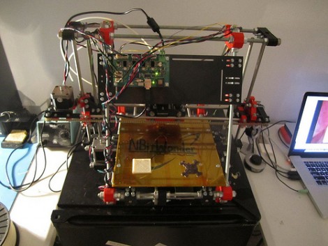
Pick and place machines are marvels of modern technology. They the can lift, orient, align and drop tiny electronic components onto a circuit board that is headed for the reflow oven. On an industrial scale they move so fast it’s a blur in front of your eyes, and they use imaging to ensure proper placement. But that kind of specialized equipment is going to cost a real bundle of money. [Bootstrap] is working on a design that will still be feature-rich, but will allow you to purchase your own pick-and-place machine for under $1000.

The design calls for a two-headed beast. One head is a vacuum tweezers which is capable of moving the parts. The other is a digital microscope that is used for precise positioning. The two heads pivot in and out of place, but it’s the table which holds the PCB that is responsible for positioning the parts. Although there’s nothing built yet, the depth of information that [Bootstrap] published in his post is impressive. He’d like your help making sure there’s no errors in the design before he builds the first three prototypes. If you’re a Solidworks guru he’ll even send you the files upon request.

We’ve seen a couple of different pick and place machines lately so take another look if you missed them the first time.

[via Adafruit]

3 Axis Plotter Made From Spare Parts

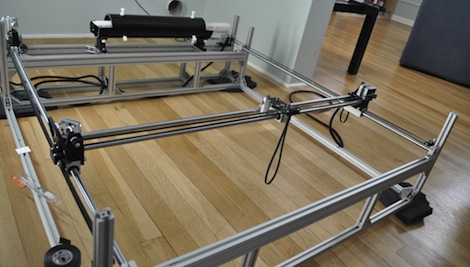
The plotter featured above was, according to the author, made almost entirely of salvaged parts. In addition to what he had accumulated, only $20 in parts was needed to complete this build. Pretty good considering the thousands of dollars that a new plotter goes for.

Control of all axes is accomplished using unipolar stepper motors.  In this case only one unipolar motor was available along with two bipolar motors. [Lovro] actually hacked these into a unipolar setup to save costs on the build.

Mach3 control software along with a parallel port is used to control the steppers. A similar “junk” setup could be used to power a CNC mill or laser engraver, so think twice before tossing that old printer in the trash!  Check out the video of this plotter in action after the break! Also, see this hack for a similar laser engraving machine using Mach3 control software. Continue reading “3 Axis Plotter Made From Spare Parts”

Automated Scanning For A Pile Of Documents

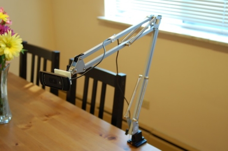
The Gado project is part of the Johns Hopkins University Center for African Studies. It has been tasked with archiving documents having to do with the East Baltimore Oral Histories Project. In short, they’ve got a pile of old pictures and documents that they want digitized but are not easily run through a page-fed scanner because they are fragile and not standard sizes. The rig seen above is an automated scanner which picks up a document from the black bin on the left, places it on the flat-bed scanner seen in the middle, and moves it to the black bin on the right once it has been scanned. It’s not fast, but it’s a cheap build (great if you’ve got a tight budgt) and it seems to work.

The machine is basically a three-axis CNC assembly. Above you can see one motor which lifts the lid of the scanner. You can’t see the document gripper in this image, but check the video after the break which shows the machine in action. A vacuum powered suction cup moves on a gantry (y-axis) but is also able to adjust its height (z-axis) and distance perpendicular to the gantry (x-axis) in order to grab one page at a time.

The pictures on the build log have captions to give you an idea of how this was built. We didn’t see any info about post-processing but let’s hope they have an auto-crop and auto-deskew filter in place to really make this automatic.

Continue reading “Automated Scanning For A Pile Of Documents”

Tripod CNC Plotter

tripod printer machine

Although some may have heard of a machine like this, the CNC tripod remains an unknown machine to many in the engineering word.  This particular machine is set up as a plotter, drawing incredibly straight lines, shapes, and letters.

The machine appears to have 6 servo motors, 3 working as pairs.  This would simplify control and allows the pen to be held at a perpendicular angle to the paper.  Once could envision this being used with, instead of a pen, a spindle and mill.  Instead of the traditional movement of a CNC mill or router, this could be used to cut out complex shapes.

Additionally, if the servos were not driven in 3 tandem pairs, but were all controlled independently, it should be possible to twist the tool in a controlled angular direction.  This would add an extra axis of control to an already robust CNC setup.  It will be exciting to see how this technology develops in the future.  Until then, check out the video after the break: Continue reading “Tripod CNC Plotter”

Crosshair Aiming System For Your Laser Cutter

diy_laser_crosshairs

[Rich] was having quite a bit of fun with his newly-acquired laser cutter, but was not impressed by the stock aiming laser that came with it. The problem with the built-in laser is that it did not actually follow the cutting laser’s path – instead, it has to be calibrated for a fixed focal length. This becomes problematic when engraving and cutting since they require different focal lengths, so it becomes a guessing game as to where the cutting laser will actually end up in respect to the aiming laser.

An additional optic module that solves this problem can be had for about $300, but after sinking $2500 into the laser setup, [Rich] was not inclined to purchase one. Instead, he bought a pair of cheap laser levels online and scavenged the line lens from one module, which was mounted on the laser cutter’s existing aiming laser. The second module was epoxied to the top of the cutting head, to create a set of cross hairs on the work surface.

As you can see in the video below, the hack works quite well, and the lasers are accurate at a variety of different focal lengths.

Continue reading “Crosshair Aiming System For Your Laser Cutter”

3D Printer Looks Factory Made

[Richard Sum] came up with a great looking 3D printer and put his project up as a campaign on IndieGoGo.

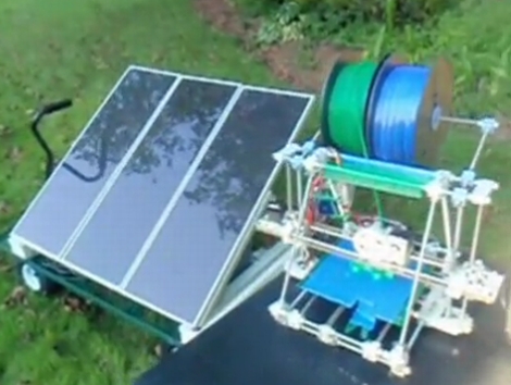
[Richard]’s ‘SUMPOD’ is based off the reprap like a lot of other 3D printers, but the SUMPOD has a look of professionalism to it; the printer looks like something that would come from a factory. We think a lot of thought went into the design and fabrication of this printer.

The specs of the machine aren’t too bad either. It’s build area is 150x150x100 mm, or nearly 2 inches than the Makerbot Thing-O-Matic. We asked [Richard] about the drive system of the machine, and he told us there is a linear bearing/belt setup for the x and y axes with a screw drive for the z axis. The electronics are standard NEMA 17 motors and reprap RAMPS fare, so everything electrical is tried and true.

[Richard] plans on adding a Dremel attachment for pcb and lithophane milling. We hope that some design files of the SUMPOD released, but in the mean time we’re really looking forward to seeing the progress of this project.

DIY CNC Touch Probe

diy_cnc_touchprobe

[Dennis] recently invested some money in the Tormach Tooling System for his CNC’d Sieg SX3 mill in order to make his tool changes easier. While the kit allows him to easily account for height offsets while changing tools, he has no quick, reliable means of locating the spindle in relation to his workpiece. Tired of manually finding the edges of his workpiece for each axis, he built himself a DIY touch probe to automate the process.

The theory behind the probe’s operation is pretty simple. In the probe’s housing, three conductive rods are mounted perpendicular to the probe tip. Each rod rests between two metal balls forming a complete circuit. When the probe touches the edge of his milling material, the circuit is broken, sending a signal to his CNC control box.

The probe is comprised of several different parts, milled from either aluminum or black delrin. [Dennis] says that after everything was assembled, the runout on the probe was unacceptable, so he made a few tweaks, and now the runout has been reduced to about 0.00025” – well within acceptable tolerance limits for any work he will be doing.

Be sure to check out his site, as there are plenty more pictures of the probe’s construction, as well as additional video.

In the meantime, continue reading to see a quick video of the finished probe in action.

Continue reading “DIY CNC Touch Probe”