We thought we’d seen it all. All the ways to drive WS2811/2812 “Neopixel” LEDs, that is. And then [Steve Hardy] comes up with a new one: hacking a computer’s VGA output to drive 500 WS2811s in a string. And it’s quite a hack. You can check out the video (it’s worth enduring the horrible wind noise) below the break.
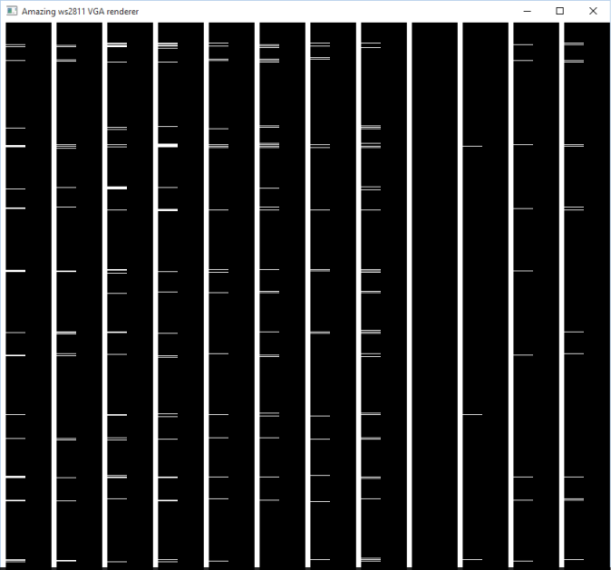 [Steve]’s big realization was that he could send the digital data that the Neopixels needed by carefully selecting a resolution and clock rate for the VGA to match the timings that the WS2811 modules wanted. A resolution of 840×1000 at 28MHz produces 70 pixels per WS2811 bit, or 12 bits per line. This means two VGA lines need to be sent for the RGB triple for each LED, hence the 1000 rows.
There are some further tricks before [Steve] got around to writing a custom OpenGL shader that converts regular graphics to his strange black-and-white bit pattern to drive the LEDs, but you’re going to have to read [Steve’s] blog for all that. If you’re waiting for a full code write-up, [Steve] says that one’s pending.
We’re just stoked to see the computing power that lies within a video card used for other purposes. Once you think of the VGA output as a general-purpose high speed (analog!) output, it opens up a whole bunch of possibilities if you can write the corresponding video software. As [Steve] points out, he’s only using the red channel right now — he could trivially add another 1000 LEDs just by tweaking his video code.


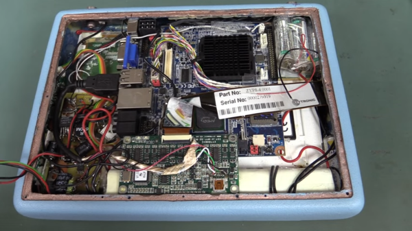
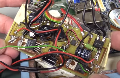 The tablet is based upon an off-the-shelf embedded PC motherboard and touchscreen controller. [Dave] took some offense at the hacked up USB connector on the touchscreen. We have to disagree with [Dave] a bit here, as the video seems to show that a standard mini-b connector wouldn’t have fit inside the tablet’s case. There’s no excuse for the USB cable shield draped over the bare touch controller board though. Things go downhill from there. The tablet’s power supply is best described as a bizarre mess. Rather than use a premade DC to DC converter, whoever built this spun their own switch mode power supply on a home etched board. The etching job looks good, but everything else, including the solder job, is beyond terrible. All the jumps and oddly placed components make it look like a random board from the junk bin was used to build this supply.


