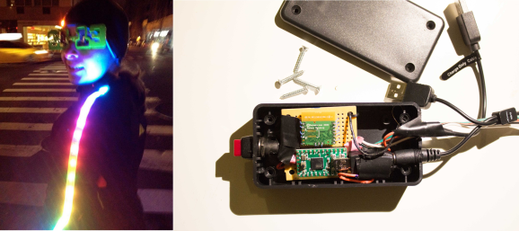
 [Miria] was tired of tangling with bicyclists on her nighttime runs. It was obvious to her to illuminate herself, but she thought it would be really cool if the lights responded to her heart rate. The short summary that tipped us off is over at NYC Resistor, and [Miria] gives the gory details on her blog. The LEDs operate in seven different light modes that increase in speed proportionate to her heart rate.
She started the build around an Arduino but found that the compatible heart rate sensors were mostly optical and gave inaccurate readings. Since she was already using a Garmin GPS watch and heart rate monitor band, she decided to hack into the conversation between the two. Garmin uses the ANT protocol for this. While [Miria] found the documentation to be an effective sleeping pill, she also found that SparkFun has an ANT transceiver breakout board. Unfortunately, it’s been discontinued.
[Miria] continued undeterred, using the SparkFun board for prototyping. Her final version uses a Teensy 2.0 and this ANT transceiver in place of the ill-fated SparkFun board. She found an Energizer power pack that plugs directly into the Teensy and can power both Adafruit weatherproof LED strips for about an hour. Look both ways, and check out her demo after the break.
Continue reading “Stop Traffic In This 7-Mode LED Running Jacket”
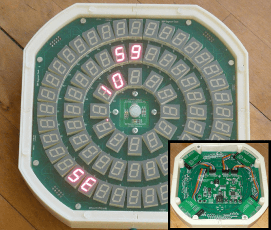
 It must be nice to be one of [kiu]’s colleagues. Some people pass out chocolates or stress balls at work as Christmas gifts, but [kiu]