Mini LED Message Board Built From Retro Displays

personal_electronic_retro_telegram

[Iain] is getting to the point in his life where he finds himself waxing nostalgic about various different technologies from his youth. One item he has always been fond of is first generation 7 segment consumer LED displays, like those found in old calculators.

He was excited to find one of these displays at the bottom of a box full of electronics odds and ends he received from a friend. After identifying the display and tracking down a data sheet online, he decided that he wanted to build some sort of little gadget out of it.

His first inclination was to build a tiny text scrolling gadget from the display, and thus his “Personal Electronic Retro Telegram” (P.E.R.T) was born. With Arduino in hand, he prototyped the circuit on a breadboard, then sent away to have some PCBs built. Once he received the boards, alll of his prototyping components were swapped out with SMD versions, including a TQFP ATMega168 chip in place of the full-sized Arduino board.

The final result is a nice melding old and new technology which he decided to give to his girlfriend as a gift. Continue reading to see a quick video of the P.E.R.T in action.

Continue reading “Mini LED Message Board Built From Retro Displays”

Hacking Cakes With LEDs

led_cake

A large part of science is making mistakes and learning from them in order to make each subsequent design that much better. When your experimentation involves hacking cakes, each failure is an exercise in deliciousness.

[Craig] and his group of research partners often bake electronics-related cakes whenever part of the team departs in search of other opportunities. Over the years, farewell parties have seen renditions of anything from multimeters to quantum computers. This time around, he wanted to make something that contained actual electronics parts, while still remaining edible.

He settled on making an LED matrix inside of a cake, using silver foil wrapped licorice for wires. In the end however, he found the silver foil to be incredibly difficult to work with, and the matrix ended up being little more than a few randomly blinking LEDs.

Even though things didn’t work out quite how he planned, he is not discouraged. The cake was still quite tasty, and through this process he has discovered edible silver paint, which will undoubtedly make it into the next farewell cake.

Larson Scanner Using 7400 Series Logic Hardware

[RandomTask] is sharing a Larson scanner he built a few decades ago. These days you can whip one of these up using an Arduino in under an hour. He mentions this, but we agree that for nostalgic purposes there’s nothing like implementing the scanning LED effect using hardware.

Often called a Cylon Eye (after the television show Battlestar Gallactica) or referred to as the lights on the front of Kitt (the car from Knight Rider), the effect doesn’t just involve switching LEDs on and off in the proper order. A true Larson Scanner fades the LEDs as the bright point moves away from them, resulting in a tail that dims over time.

This implementation uses a 555 timer as the clock signal, allowing for speed control through a potentiometer. A counter chip, J-K flipflop, and line decoder all work with each other to address the movement of the brightest light. The fading effect is managed via a capacitor and resistor for each LED. The video after the break shows the pleasing result of this setup.

Continue reading “Larson Scanner Using 7400 Series Logic Hardware”

Build A Spinning POV In A Day

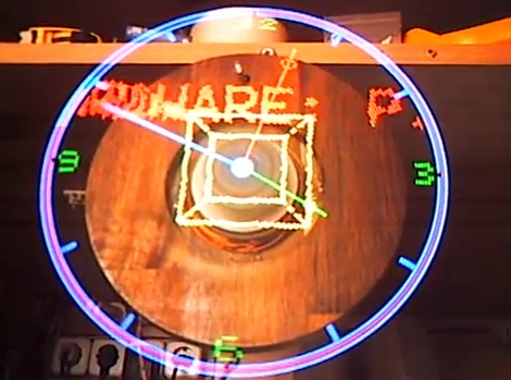
We love spinning POV displays but have yet to build one to call our very own. This project might be the one that we end up building. It’s looks good and it’s the only persistence of vision display that comes to mind which can be built in twelve hours.

The spinning is taken care of by a PC fan. This actually helps with some of the calculations as this fan spins at a know RPM. That information, along with a bit of geometry, can be used to calculate the timer interrupts for syncing the display. A reference point for this device is provided by an IR receiver/emitter pair which is easy to wire up since you already need a voltage source for the fan itself. The rest of the hardware is pretty common: a battery holder is centered on the axis for proper weight distribution and protoboard houses the components such as a PIC 18F252, 74LS373 data latches, and the LEDs themselves. The circuit is wire-wrapped, and works like a charm as evidenced in the clip after the break.

Continue reading “Build A Spinning POV In A Day”

Guitar Teaches You To Play Using LEDs

guitarduino

[Andrew] is an electrical engineering student at UIC, and decided that he would build a MIDI guitar for his senior design project. After tinkering for awhile, things were not looking good, and the MIDI guitar idea was scrapped. With his deadline creeping up, he came up with a new idea, the Guitarduino. His new project is a guitar that teaches you how to play chords and scales by showing you the proper notes to play via LEDs embedded in the guitar’s neck.

He removed the neck, and carefully drilled the holes that would eventually house his 130+ LEDs. The LEDs were wired to his Arduino via some multiplexing circuitry that resides on the back of the guitar’s body. The Arduino was mounted on the front of the guitar along with a shield used for communicating with his LED array. He built another shield that serves as the LCD display as well as the input board for his guitar.

The final result of all his work is fantastic. The user simply needs to dial in the chord or scale that he wants to learn, and the guitar lights up, showing the proper finger positions on the fretboard. We could see this coming in quite handy for anyone just starting to learn how to play.

Check out the video below to see a demonstration and walkthrough [Andrew] put together highlighting his guitar’s features.

Continue reading “Guitar Teaches You To Play Using LEDs”

Pinewood Derby Cars Have Come A Long Way

Get your graphite and hike a wheel, [Aron Hoekstra] writes in to completely embarrass us with some excellent pinewood derby cars.    In the pursuit of that extra something [Aron] consulted with his sons who came up with some cool ideas for cars, one Tron themed and the other basically a Wiimote with wheels! The official Pinewood derby rules say nothing about electronics, so as long as nothing helps the block-o-wood travel down the track faster, anything goes. This means you are free to load up whatever cool lights you want, but will have to earn your robotics merit badge some other way.

[Aron] Starts the builds by carving out the shape of the cars, each feature a hollowed out cavity underneath to accommodate the batteries and electronics. For the Tron Light Runner car, one continuous EL strip weaves in and out of the derby car’s body, and a single AAA battery runs the driver. [Aron] notes that it took around five feet of EL wire to cover the little car, which is two more than the driver is rated for. Fortunately the extra little bit of additional wire had little effect on its brightness.

The Wiimote car has detailed 3d buttons, a breadboard with a linear regulator,  and PIC 16F628 driving  blue LEDs.  For the majority of the time the PIC simply runs a chase routine for the four LEDs, but [Aron] went through the trouble to program in the Wiimote’s start-up sequence!

Shown above the [Hokestra]’s work is my older brother’s pinewood derby car (top left) and my… potato rocket… thing… (top right)  from many many years ago. I now seriously regret not considering LEDs! Although I think all that existed then was red,  green and IR.

Check out videos of the [Hoekstra] bros’ cars after the jump!

Continue reading “Pinewood Derby Cars Have Come A Long Way”

build_status_board

LED Build Monitor Helps Keep An Eye On Your Servers

In his line of work, Hackaday reader [Pedantite] often has to monitor the build status of several continuous integration servers throughout the day. One afternoon, he got the idea to install a set of stop lights in the office in order to monitor the status of the servers, but filed it away as a “wouldn’t it be cool if…” project.

After some time had passed, he was bitten by the idea bug again and decided he would build a physical device to display the status of his build processes. This time around, he brainstormed on a smaller scale and the result is the “Indictron” you see above.

He built a simple LED board made up of four rows of four LEDs to display the build processes. Different LEDs are lit depending on the project’s current build status as well as the results of the previous build. The board uses an ATmega88, and interfaces with a compiler watchdog application using a virtual USB package made specifically for AVR micro controllers.

The end result is a simple, yet useful status board that “just works”. He does not seem to have code or schematics posted on his site at the moment, but we’re pretty sure he would share them upon request.

If you’re interested in a bit more of [Pedantite’s] work, check out his “Good Times” parental timer we featured last week.