We love lamps here at Hackaday, especially if they imitate natural light sources. [Scott McIndoe] used his love of lamps to fashion a chandelier replicating his favorite constellation, the Southern Cross.
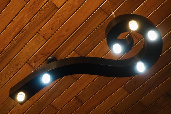
Starting with the Southern Cross’s four major stars and the pointers of Alpha and Beta Centauri, [McIndoe] sketched out a breaking wave form between the six stars to form the spine of this light source. By using smart bulbs for each of the six star positions, he was able to set a scene that replicates the color and relative brightness of each star for that extra astronomical touch.
The top and bottom of the chandelier is laser cut from 3 mm plywood and fitted together using glue and finger joints while the sides are a wood veneer. The entire piece was sanded and coated with a bit of filler before painting. Mounting is accomplished using three eye hooks mounted on the top side of the chandelier.
If you want more celestial lamps, check out [McIndoe]’s previously-featured analemma chandelier or this lithophane moon lamp.