Extensive research shows that tobacco kills. This is common knowledge as of late, which has prompted a flurry of anti-smoking ads to flood in. Regular smokers are now reconsidering their smoking patterns and are looking at healthier alternatives. Among those options are electronic cigarettes that vaporize flavorful liquid into smooth drags of smoke.
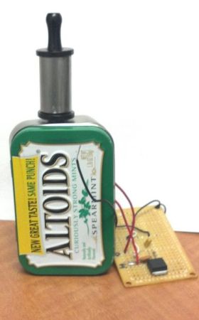
Prices for these devices can range anywhere from $40 to $240, which can be quite expensive for those on a budget. So instead of buying one, [MrRedBeard] decided to create his own DIY electronic cigarette contraption out of an Altoids can.
The approximate cost (not including batteries) is about $12. This covers the 5 Amp adjustable voltage regulator and the 500 ohm potentiometer that is best used for a rig like this. The wattage is what drives the heat giving it a more consistent vapor stream of cloud smoke.
For more e-cigarette hacks, check out these ones powered by an NES controller and this vaporizer that can send smells…in space!
 [Nick]’s grandfather was quite the old school hacker. In the 1940s, he built his own wire recorder and microphone to capture everything from his children’s Chirstmas wishes to his favorite songs and programs from the radio. Only 20 or so spools have survived and were doomed to silence until [Nick] was able to