Lathe CNC Upgrade Is Nothing To Shake A Turned Stick At

7x12 CNC Lathe Conversion

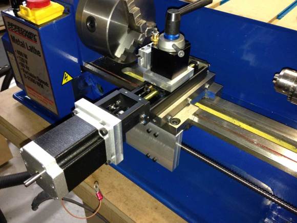
We see a lot of CNC Machines here on Hackaday but not too many of them are lathe-based. [Jim] sent us an email letting us know his dissatisfaction regarding the lack of CNC Lathes and included a link to one of his recent projects, converting a small manual lathe to computer control. This isn’t some ‘slap on some steppers‘ type of project, it’s a full-fledged build capable of tight tolerances and threading.

The project is based on a 7×12 Mini Lathe. There are several brands to choose from and they are almost identical. Check out this comparison. [Jim] started with Homier brand.

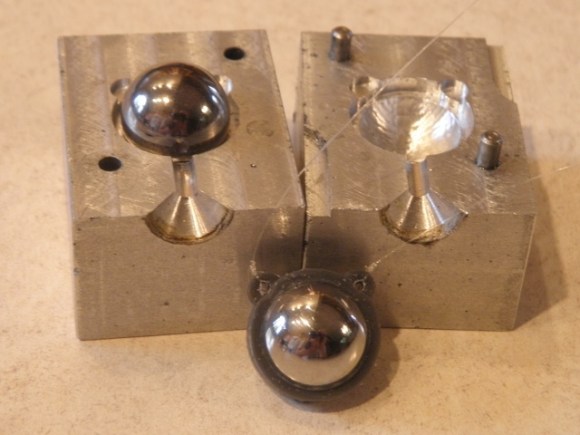
The first thing to get upgraded was not related to the CNC conversion. The 3″ chuck was replaced with a 5″. Changing it over was easy using an adapter plate made for the task. For the X Axis, the stock ways and lead screw were removed and replaced by a THK linear slide. This slide only has 2.5″ of travel and is perfect for this application. The travel being so short allowed the final eBay auction price to be under $40.

Continue reading “Lathe CNC Upgrade Is Nothing To Shake A Turned Stick At”

A Bicycle Built For One

diyBike

[Bcmanucd] must have been vying for husband of the year when he set out to build his wife a custom time trials bicycle. We’re not just talking about bolting together a few parts either – he designed, cut, welded, and painted the entire frame from scratch. Time trial racing is a very specific form of bicycle racing. Bikes are built for speed, but drafting is not allowed, so aerodynamics of the bike and rider become key. Custom bikes cost many thousands of dollars, but as poor college students, neither [Bcmanucd] nor his wife could afford a proper bike. Thus the bicycle project was born.

[Bcmanucd] created the basic geometry on a fit assessment provided by his wife’s cycling coach. He designed the entire bike in Autodesk Inventor. Once the design was complete, it was time to order materials. 7005 aluminum alloy was chosen because it wouldn’t require solution heat treating, just a trip to the oven to relieve welding stresses. Every tube utilized a unique cross section to reduce drag, so [Bcmanucd] had to order his raw material from specialty bike suppliers.

Once all the material was in, [Bcmanucd] put his mechanical engineering degree aside and put on his work gloves. Like all students, he had access to the UC Davis machine shop. He used the shop’s CNC modified Bridgeport mill to cut the head tube and dropouts.

The most delicate part of the process is aligning all the parts and welding. Not a problem for [Bcmanucd], as  he used a laser table and his own jigs to keep everything lined up perfectly. Any welder will tell you that working with aluminum takes some experience. Since this was [Bcmanucd’s] first major aluminum project, he ran several tests on scrap metal to ensure he had the right setup on his TIG welder. The welds cleaned up nicely and proved to be strong.

The entire build took about 3 months, which was just in time for the first race of the season. In fact, during the first few races the bike wasn’t even painted yet. [Bcmanucd’s] wife didn’t seem to mind though, as she rode it to win the woman’s team time trial national championships that year. The bike went on to become a “rolling resume” for [Bcmanucd], and helped him land his dream job in the bicycle industry.

Echoing the top comment over on [Bcmanucd’s] Reddit thread, we’d like to say awesome job — but slow down, you’re making all us lazy spouses look bad!

A Tweeting Litter Box

SmartLitterBox

How can you not be interested in a project that uses load cells, Bluetooth, a Raspberry Pi, and Twitter. Even for those of our readers without a cat, [Scott’s] tweeting litter box is worth the read.

Each aspect of this project can be re-purposed for almost any application. The inexpensive load cells, which available from eBay and other retailers, is used to sense when a cat is inside the litter box. Typically sensors like the load cell (that contain a strain gauge) this use a Wheatstone bridge, which is very important for maximizing the sensitivity of resistive sensor. The output then goes to a HX711, which is an ADC specifically built for load cells. A simple alternative would be using an instrumentation amplifier and the built-in ADC of the Arduino. Now, the magic happens. The weight reading is transmitted via an HC-06 Bluetooth module to a Raspberry Pi. Using a simple Perl script, the excreted weight, duration, and the cat’s resulting body weight is then tweeted!

Very nice work! This is a well thought out project that we could see being expanded to recognize the difference between multiple cats (or any other animal that goes inside).

THP Entry: OpenMV

OpenMV

The future is a scary place, full of robots, drones, and smart appliances with cameras and vision systems that will follow your dog, your child, or your face around, dutifully logging everything they see, reporting back to servers, and compiling huge datasets that can be sold to marketing companies. We’re not too keen on this view of the future, but the tech behind it – cheap cameras in everything – is very cool. [Ibrahim] is doing his part to bring about the age of cheap cameras that are easy to interface with his entry to The Hackaday Prize, the OpenMV.

The idea of a digital camera that is easy to interface with microcontrollers and single board computers isn’t new. There are serial JPEG cameras and the CMUcam5 Pixy, but they cost somewhere around $70. It’s not something you would design a product around. [Ibrahim]’s OpenMV costs about $15, and offers some interesting features like on-board image processing, a huge amount of RAM, and even a wireless expansion thanks to TI’s CC3000 WiFi module.

Currently, the OpenMV is capable of doing face detection at 25fps, color detection at better than 30fps, all thanks to the STM32F4 ARM micro running at 180MHz. There’s support for up to 64MB of RAM on board, with IO available through serial, SPI, I2C, USB 2.0, and WiFi.

It’s an interesting project on its own, but the really cool thing about this build is the price: if [Ibrahim] can actually produce these things for $15 a pop, he has an actual product on his hands, one that could easily be stuffed inside a drone or refrigerator for whatever cool – or nefarious – purposes you can imagine.


SpaceWrencherThe project featured in this post is an entry in The Hackaday Prize. Build something awesome and win a trip to space or hundreds of other prizes.

Droning On: Choosing A Flight Controller

do4 The flight controller is the nerve center of a drone. Drone flight control systems are many and varied. From GPS enabled autopilot systems flown via two way telemetry links to basic stabilization systems using hobby grade radio control hardware, there is an open source project for you.

Modern drone flight controllers can trace their roots back to R/C helicopters. Historically, R/C planes were controlled directly by the pilot’s radio. Helicopters added a new wrinkle to the mix: tail rotors. Helicopters use their tail (or anti-torque) rotor to counteract the torque of the main rotor attempting to spin the entire helicopter’s body. It all works great when the helicopter is hovering, but what about when the pilot throttles up to fly out? As the pilot throttles up, the torque increases, which causes the entire helicopter to do a pirouette or two, until the torque levels out again. The effect has caused more than one beginner pilot to come nose to nose with their R/C heli.

The solution to this problem was gyroscopes, heavy brass spinning weights that tilted in response to the helicopter’s motion. A hall effect sensor would detect that tilt and command the tail rotor to counteract the helicopter’s rotation. As the years wore on, mechanical gyros were replaced by solid state MEMS gyros. Microcontrollers entered the picture and brought with them advanced processing techniques. Heading hold gyros were then introduced. Whereas older “rate only” gyros would drift, weathervane, and wiggle, heading hold gyros would lock down the helicopter’s nose until the pilot commanded a turn. These single axis flight controllers were quickly adopted by the R/C helicopter community.

Today’s flight control systems have many sensors available to them – GPS, barometric pressure sensors, airspeed sensors, the list goes on. The major contributors to the flight calculations are still the gyros, coupled with accelerometers. As the name implies, accelerometers measure acceleration – be it due to gravity, a high G turn, or stopping force. Accelerometers aren’t enough though – An accelerometer in free fall will measure 0 G’s. Turning forces will confuse a system trying to operate solely on accelerometer data. That’s where gyros come in. Gyros measure rate of rotation about an axis. Just as our helicopter example above covered yaw, gyros can be used to measure pitch and roll of an aircraft. A great comparison of gyros and accelerometers is presented in this video from InvenSense.

Stay with us after the break for a tour of available flight controllers and what each adds to the mix. Continue reading “Droning On: Choosing A Flight Controller”

The Hovering, Holographic, Star Wars Display

Tweetergif

While we’re still a long way off from the Star Wars telepresence holographic displays, this build over on the Projects site is the closest we’ve seen yet. Even better, it can be built in a garage for not much money.

Inside the Hoverlay are a few fans and a pair of ultrasonic atomizers that turn water into an extremely fine mist. The fans pull this vapor up through the base of the display and through simple drinking straws to create a laminar sheet of water vapor. Put a projector behind this thin sheet of vapor, and you have a display, seemingly floating in mid-air.

The base of the display can be scaled up, simply by putting several units together in a line. It’s still just a prototype – future versions will improve the stability and reduce the thickness of the fog layer – but it’s still a very cool build for a custom holographic display.

Continue reading “The Hovering, Holographic, Star Wars Display”

DIY Newton’s Cradle Uses Parts Designed On A Smart Phone

Injection Molded Parts

As far as physics demonstrations go, the Newton’s Cradle is probably one of the most recognizable. Named after Sir Isaac Newton, the Newton’s Cradle demonstrates the law of conservation of momentum using swinging ball bearings.

[Scorchworks] decided he wanted to build his own Newton’s Cradle. The frame appears to be cut from MDF or particle board and then screwed together. That material is really easy to obtain and also to work with using inexpensive tools. The tricky part was the ball bearings. Most of the time when you see a Newton’s Cradle, the ball bearings have a small hole drilled in the top with an eye hook attached. The string is then attached to the eye hook.

[Scorchworks] decided to do something different. His plan was to make custom injection molded plastic rings that would fit perfectly around the ball bearings. The most interesting thing is that he designed the injection molding plates entirely on his smart phone while at his child’s baseball practice. To do this, [Scorchworks] used his own Android app, ScorchCAD. ScorchCAD is a free clone of OpenSCAD that is designed to run on Android devices. Most of the functionality of OpenSCAD has been implemented in ScorchCAD, though not all functions work yet. You can find a list of all the supported functions on the project’s website or in the Google Play store.

Once the plates were designed within ScorchCAD, [Scorchworks] exported the STL file and then used Meshcam to generate the gcode for his CNC milling machine. Once he had the plates machined, he just placed the ball bearing into the mold and injected the molten plastic around it. The plastic formed a perfectly shaped ring around the bearing with small loops for the string. [Scorchworks] repeated the process several times to get all of the ball bearings finished.

Finally, the bearings were strung up using some fishing line. A Newton’s Cradle is very sensitive to the positioning of the ball bearings. To account for this, [Scorchworks] tied each end of the fishing line to two different screws on top of the cradle. This way, each screw can be tightened or loosened to adjust the position of each ball bearing.