Bluetooth Headphones For Hearing Aids

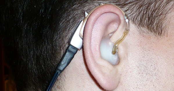
Cyborgs walk among us, but for the time being, it’s really only people with glasses, contact lenses, the occasional hearing aid and the infrequent prosthesis. As with all technology, these devices can be expanded into something they were not originally designed to do – in [Gertlex]’ case, the superpower of listening to music through his hearing aids. he gets a few strange looks from wearing a Bluetooth headset around his neck, but the power to turn his hearing aids ito what are effectively in-ear monitors is a great application of modified electronics.

[Gertlex] began with a Bluetooth headset, his hearing aid, a few resistors, some wire, a 3.5mm audio connector, and an absurdly expensive DAI cable. The DAI cable – Direct Audio Input – is a pseudo-standardized feature on many hearing aids. as its name implies, it allows the wearer of a hearing aid to pipe audio directly into their ear.

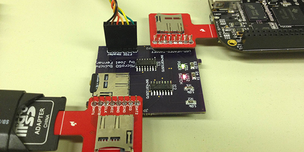
By cutting up one of these $50+ DAI cables, [Gertlex] was able to construct a DAI to 3.5mm adapter cable. From there, it was simply a matter of installing a 3.5mm socket on a Bluetooth headset.

It’s a brilliant build, with the most expensive component being the DAI connector itself. [Gertlex] has a few ideas for making these connectors himself – they’re really only three pins and some plastic – and we’re hoping he gets around to that soon.


The In-Circuit SD Card Switch

SDISP

For nearly every problem, it’s possible to engineer a solution, even if you’re dealing with an extraordinarily niche problem that might only apply to yourself. [Joel] wanted to be able to program the microSD card in his BeagleBone with a new bootloader or file system without removing the SD card from the target board. This is a peculiar requirement, and it’s highly doubtful a product or even a circuit exists for such a function. This meant [Joel] would need to roll his own board to accomplish the task.

The board is remarkably simple, housing a single microSD socket, two expansion headers for a microSD sniffer for a computer and an embedded board, an FTDI header, and a pair of 4-bit multiplexer/demultiplexers. The operation of the device is fairly straightforward: send a signal down the FTDI cable, and the board switches the onboard SD card from one device to another.

[Joel] has a video of his screen that shows him pulling off in-circuit SD card reading and writing. You can check that out below.

Continue reading “The In-Circuit SD Card Switch”

Hackaday Links: June 8, 2014

hackaday-links-chain

Yes, dogfighting with RC planes is cool. You know what’s even cooler? RC jousting. Considering these eight foot long planes are probably made of foam board or Depron, they’ll probably hold up for a fairly long time. The perfect application of RC FPV.

Home automation is the next big thing, apparently, but it’s been around for much longer than iPhones and Bluetooth controllable outlets and smart thermostats. Here’s a home automation system from 1985. Monochrome CRT display panel (with an awesome infrared touch screen setup), a rat’s nest of wiring, and a floor plan drawn in ASCII characters. It’s also Y2K compliant.

Here’s an idea for mobile component storage: bags. Instead of tackle and tool boxes for moving resistors and other components around, [Darcy] is using custom bags made from polyethylene sheets, folded and sealed with an impulse sealer. It’s not ESD safe, but accidentally zapping a LED with an ESD would be impressive.

Need a stepper motor test circuit? Easy, just grab one of those Polulu motor drivers, an ATtiny85, wire it up, and you’re done. Of course then you’re troubled with people on the Internet saying you could have done it with a 555 timer. This one is for them. It’s a 555, some wire, and some solder. Could have done it with discrete transistors, though.

Someone figured out Lego Minifigs can hold iDevice charge cables. +1 for the 1980s spaceman.

Remember that “electronic, color sensing, multicolor pen” idea that went around the Internet a year or so ago? It’s soon to be a Kickstarter, and man, is this thing full of fail. They’re putting an ARM 9 CPU in a pen. A pen with a diameter of 15mm. Does anyone know if an ARM 9 is made in that small of a package? We’ll have a full, “this is a totally unrealistic Kickstarter and you’re all sheep for backing it” post when it finally launches. Also, this.

The Open Hardware Driver For CRTs

driver
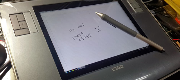
CRTs are the king of displays for any homebrew project. They have everything – high voltages, high vacuums, X-rays, and the potential for a vector display – that makes a project exude cool. Getting an old CRT up and running, though, that’s another story. Never rear, because now there’s an Open Hardware eletrostatic CRT driver for your next display.

[Eric] designed a driver circuit that should be able to send a picture to most 2″, 3″ and some 5″ electrostatic CRTs, the kind found in ancient TVs and oscilloscopes. The 1kV power supply uses a transformer usually found in a CCFL bulb, and is able to produce several milliamps. You’ll want to keep one hand behind your back when working on this.

The driver circuit takes a 0-3.3V analog signal for deflecting the beam along the X and Y axis. The amplifier has enough bandwidth to handle NTSC video, so displaying video along with vector letters and shapes is also a possibility with this circuit. Most of the files are available on the git, with three boards available to be ordered from OSHPark.
Thanks [Mike] for the tip.

Converting The Wacom Intuos Into A Cintiq

wacom

Wacom, purveyors of fine pen tablets for digital artists, basically have two product lines of pen tablets. The first, Intuos, is a great pen tablet that give an artist the ability to turn a computer into a virtual dead tree notebook. The second product line, the Cintiq, takes the same technology and adds an LCD to the mix, effectively turning a drawing tablet into a second display. [Bumhee] wanted a Cintiq, but didn’t want to pay the Cintiq price, leading him to install a display in his old Intuos tablet. It’s an amazingly simple build, making us think we’ll be seeing a few derivatives of his work in the future.

The display [Bumhee] used for this modification is a Retina display from an iPad. With the right adapter, you can easily connect one of these displays to a computer, giving you a very thin 2048×1536 9.7″ display. The initial tests to see if this mod would work on his tablet – removing the metal shield on the display, placing it on the tablet, and drawing – were a success, giving [Bumhee] the confidence to irreparably modify his tablet.

From there, the modification was a simple matter of cutting up the enclosure of the tablet, installing the display with a few screws, and installing a piece of glass over the display. Very easy, and it’s just about the only way you’re going to get a pen tablet with a small, high-resolution display for less than a thousand dollars.

Thanks [David] for sending this one in.

The Development Of A Hardware Random Number Generator

rng

[Ian] had a need for a lot of random numbers. There are dozens of commercial offerings when it comes to RNGs, but there are also hundreds of different ways for an electronics hobbyist to shoot random bits at a serial port. One of these methods is an RNG based on the avalanche breakdown noise in a PN junction. As with any circuit in hobbyist electronics, there are dozens of prototypes floating out there on the web, but not too many finished projects. [Ian] decided he would build one of these RNGs as a prototype and bring it to something resembling a finished project.

An avalanche noise RNG takes advantage of the fact that a strongly reverse-biased PN junction, like one found in a transistor, will create a condition where one electron knocks another electron out of place, leading to a sustained chain reaction. It’s quantum, it’s chaotic, it makes for a great source for a random number generator, and there are already dozens of prototype circuits around the Internet.

[Ian] took one of these circuit designs by [Will Ware] and started the iterations that would lead to a finished design. Round one was a simple PCB with the basic circuit and a power supply. Just a few transistors, resistors, and a DC/DC boost converter. Confirming the circuit was generating noise, the next iteration brought in an ADC and an ARM micro with a USB interface. Iterating over this again with an improved ADC – 20 megasamples per second – the design finally reached a point where a final PCB could be designed.

In the end, [Ian] turned a simple circuit that could have been built on a breadboard into a USB device that throws 9kB/s of random data into a computer. The data are actually good, too: the project passed most of the Dieharder test suite, making it very useful for whatever crypto or gaming application [Ian] has in mind.

ISEE-3: On Track To Come Home

map
Intended trajectory from ICE team in 1986 (blue), 2001 ephemeris of ISEE-3 (white) and current ephemeris (red/green). Click to embiggen.

When last we heard of the progress of commanding the derelict ISEE-3 satellite into stable orbit between the Earth and the sun, the team had just made contact with the probe using the giant dish in Arecibo, sent a few commands, and started gathering data to plot where the spacecraft is and where it will be. A lot has happened in a week, and the team is now happy to report the spacecraft is alive and well, and much, much closer to the intended trajectory than initially believed.

Before last week, the best data on where ISEE-3 was heading was from a 13-year-old data set, leaving the project coordinators to believe a maneuver of about 50-60  m/s was necessary to put the spacecraft into the correct orbit between the Earth and the sun. With new data from Arecibo, that figure has been reduced to about 5.8 m/s, putting it extremely close to where the original ICE navigation team intended it to go, all the way back in 1986. This also gives the team a bit of breathing room; the original planned maneuver to capture the spacecraft required nearly a third of the available fuel on board. The new plan only requires the spacecraft expend about 5% of its fuel stores. This, of course, brings up the idea of continuing the planned mission of the rebooted ISEE-3 beyond the Earth-Sun L1 point, but that is very much putting the cart before the horse.

Of course, getting ranging data of the spacecraft is only a small part of what has happened with the ISEE-3 part this week. Thanks to the ‘away team’ sent to Arecibo to install hardware and attempt to make contact with the satellite, both transceivers are working, telemetry is being downloaded from the probe, and work has begun on refining the exact position of ISEE-3 to compute where and when the spacecraft needs to make its maneuver.

Regular Hackaday feature and software defined radio god [Balint] was on hand with the away team at Arecibo to install his company’s SDR unit on the largest dish on the planet. His happy dance of the first data from ISEE-3 made the blog rounds, but the presentation (PDF) and photo gallery tell the story of working on the largest dish on the planet much better.

There’s still a lot of work to be done by the ISEE-3 team as they figure out how best to capture the spacecraft and prepare for the burn in the following week. They should have the exact orbit of ISEE-3 nailed down early this week, and after that, ISEE-3 could on a path back home in less than two weeks.