DIY Injection Molder Built From A Cheap Pneumatic Press

[Kurt Schaefer] was watching YouTube videos of people making molds for injection molding purposes using what he considered to be the toy 3018 CNC machines, and looking at the results, decided he needed a piece of the action. However, once you have molds, the next obvious issue to address is lack of access to an injection molding machine. But these things are expensive. As luck would have it, you can get a nice-looking pneumatic press for less than $350, and with a little more money spent, [Kurt] found he could convert it into a functional injection molding machine (video, embedded below), and get some half-decent results out of it.

After ordering the press on eBay, what eventually arrived was quite a mess, having clearly been inadequately packed for its weight, and had sustained some damage in transit. Despite this, it seemed the functional bits were fine, so [Kurt] decided to press on with the build. The first obvious change is the requirement of a heated chamber to deal with the feedstock material. Using an off-the-shelf injection molding chamber by buster beagle 3D, only a few standoffs and a support bracket needed machining in order to complete the mechanics. A common PID controller available from the usual suppliers, with some heat bands wrapped around the chamber, dealt with the injection temperature requirements, and some 3D printed enclosures wrapped it all up neatly.

After some initial wobbles, and a couple of hacks to the design, [Kurt] got some pretty good results out of this simple setup, and it appears to be pretty tune-able and repeatable, which will help maintain the quality of those results. In short, a neat hack of easy to get parts, and perhaps a welcome addition to a hackerspace near you?

3D printed parts are available on the Thingiverse page, as well as a Fusion360 CAD model. The shopping list for parts can be found in the video description, if you want to have a go at reproducing this.

We’ve seen a few DIY injection molding attempts over the years, like this slick plastic molding setup. Here’s one with 3D-printed molds, and if you just need something the right shape, you could just injection mold with a hot glue.

Continue reading “DIY Injection Molder Built From A Cheap Pneumatic Press”

One Stepper Plus A Whole Bunch Of Magnets Equals A Unique Seven-Segment Display

Sometimes the cost of simplicity is extra complexity. It seems counterintuitive, but it seems to be true. And this single-motor mechanical seven-segment display seems to be a perfect example of this paradox.

On second thought, [aeropic]’s mechanism isn’t really all that mechanically complicated, but there sure was a lot of planning and ingenuity that went into it. The front has a 3D-printed bezel with the familiar segment cutouts, each of which is fitted with a pivoting segment, black on one side and white on the other.

Behind the bezel is a vertical shaft with three wheels, one behind each horizontal segment, and a pair of horizontal shafts, each with two wheels behind each vertical segment. The three shafts are geared to turn together by a single stepper in the base. Each wheel has ten magnets embedded in the outer circumference, with the polarity oriented to flip the segment in front of it to the right orientation for the current digit. It’s probably something that’s most easily understood by watching the video below.

We’ve seen quite a few of these mechanical seven-segment displays lately — this cam-and-servo mechanism comes to mind. We love them all, of course, but the great thing about [aeropic]’s display is how quiet it is — the stepper is mostly silent, and the segments make only a gentle clunk when they flip. It’s very satisfying.

Continue reading “One Stepper Plus A Whole Bunch Of Magnets Equals A Unique Seven-Segment Display”

You Can Find Military Radars On Publicly-Available Satellite Data

When it comes to hunting down military radar installations and associated hardware, we typically think of equipment that is firmly in the price bracket of nation states and their military forces. Whether it’s early warning radar, those used for air defence, or for naval purposes, you’d think it was relatively difficult to intercept or track these emissions.

However, a new tool built by geocomputation lecturer Ollie Ballinger shows this isn’t the case. In fact, openly-available data captured via satellite can be used to find all manner of military radar emitters. Let’s explore how!

Continue reading “You Can Find Military Radars On Publicly-Available Satellite Data”

screenshow showing the supposed AllSpice interface. It resembles the GitHub interface, and shows a pull request open to add some ESD protection to a device.

AllSpice Building A Hardware Development Ecosystem For Companies

In our “hardware development gets serious” news, we’ve recently learned about AllSpice, a startup building hardware development collaboration infrastructure for companies. Hardware developers are great at building hardware tools for themselves, but perhaps not always so when it comes to software, and AllSpice aims to fill that gap at the “hardware company” level. Nowadays, what commonly happens is that software development tools and integrations are repurposed for hardware needs, and the results aren’t always as stellar as they get in the software world. In other words, AllSpice is learning from the positive outcomes of software industry and building a platform that takes the best parts from these tools, aiming to get to similarly positive outcomes in areas where currently hardware team experiences are lacking.

What AllSpice is building seems to be an umbrella platform designed to augment, integrate and hook into a slew of different already-developed platforms like GitHub, GitLab, Jira (and some other ones), and add much-needed features that large-scale hardware developers can’t afford to maintain and develop themselves. “Design review by screenshot” isn’t unheard of in hardware circles, and likely a thing that everyone of us with hardware collaboration experience has partaken in. On a company scale, there’s a myriad of hardware-related problems like that to solve and polish over.

Continue reading “AllSpice Building A Hardware Development Ecosystem For Companies”

Here’s How Those Battery-Free Flashing Phone Stickers Worked

The late 90s and early 2000s were a breakout time for mobile phones, with cheap GSM handsets ushering in the era in which pretty much everybody had a phone. Back then, a popular way to customize one’s phone was to install a sticker that would flash when the phone rang. These required no batteries or any other connection to the phone, and [Big Clive] has dived in to explain how they worked. 

The simple schematic of the flashing sticker circuit. The flashing was generated by the pulses of RF energy from the smartphone.

It’s an old-fashioned teardown that requires a bit of cutting to get inside the sticker itself. A typical example had three LEDs in series for a total voltage drop of around 7V, hooked up to two diodes and a PCB trace antenna. A later evolution used raw unpackaged components bonded to the PCB. Future versions went down to a single diode, using the LEDs to serve as the second. The basic theory was that the PCB traces would pick up RF transmitted by the phone when a call was coming in, lighting the LEDs.

In the 2G era, the freuqencies used were on the order of 300 MHz to 1.9GHz. A combination of the change in frequencies used by modern phone technology and the lower transmit powers used by handsets means that the stickers don’t work properly with modern phones according to [Big Clive].

Incidentally, you might like to consider running your own old-school cellphone network. Video after the break.

Continue reading “Here’s How Those Battery-Free Flashing Phone Stickers Worked”

A 3D-printed mechanical system that moves weather symbols around

3D Printed Mechanical Contraption Shows Live Weather Forecast

“What’s the weather going to be like today?” is a question that’s near-permanently on the mind of those living in places like Britain, where brilliant sunshine can follow thick clouds, only to turn into drizzle an hour later. Nowadays you simply need to glance at your phone to know whether you need to pack an umbrella, but where’s the fun in that? Why not have a huge mechanical display to show you a summary of today’s weather?

As a fan of automatons and other contraptions filled with gears and pulleys, [Mike] decided to build just such a machine for his latest Mikey Makes video. It uses brightly coloured indicators inspired by the BBC’s famous “fluffy cloud” symbols that can show various combinations of sunshine, clouds, rain and snow. These symbols are moved around by dozens of gears, levers, swinging arms and other moving parts which were all 3D printed. We especially like the system that folds out rays of sunshine from behind the cloud; you can see it working in the video embedded below.

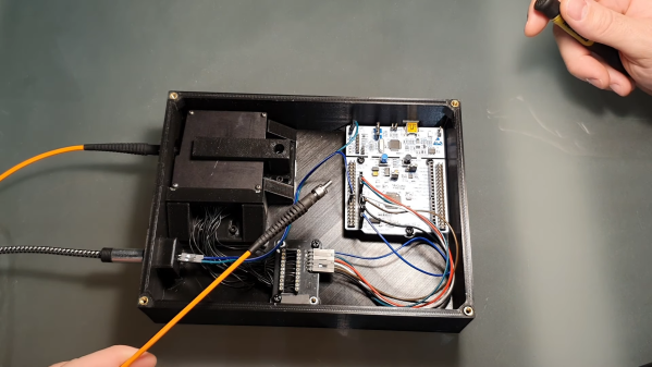
Live weather data is fetched through an open weather API by an Arduino MKR WiFi 1010. This then drives the mechanical system through a pair of motor driver ICs. The heavy work is performed by stepper motors and servos, while micro-switches and optical detectors determine the end point of each movement.

If you’re into weather displays, you’re in luck: we’ve featured many different styles over the years, including e-paper screens, analog gauges, split-flap displays and even a miniature recreation of the local weather.

Continue reading “3D Printed Mechanical Contraption Shows Live Weather Forecast”

Ray Tracing On A Modern TI Graphing Calculator

Something being impractical isn’t any reason not to do it, which is why just about anything with a CPU in it can run Doom by now. For the same reason there obviously is a way to do ray tracing of 3D scenes on a modern-day TI-84 Plus CE graphical calculator. This is excellent news for anyone who has one of these calculators, along with a lot of time, perhaps during boring classes, to spare.

As [TheScienceElf] demonstrates in a video, also embedded after the break, it’s not quite the real-time experience one would expect from an NVidia RTX 30-series GPU. Although the eZ80-based CPU in the calculator is significantly more efficient than a Z80 as found in many 1980s home computers, the demo scene at standard resolution takes about 12 minutes to render, as also noted on the GitHub project page.

Perhaps the most interesting part about this project is its use of the Clang-based C & C++ toolchain for the TI-84 Plus CE which gives easy access to the calculator’s hardware and related, including graphics, file I/O, fonts, keypad input and more. Even if using a TI-84 Plus CE to render the next Pixar-level movie isn’t the most productive use imaginable for these devices, this project and the CE toolchain make it all too easy to tinker with these $150 devices.

It would also offer a nice change of pace from writing Snake in TiBASIC, a BASIC dialect in which [TheScienceElf] incidentally has also written a ray tracer.

(Thanks to [poiuyt] for the tip)

Continue reading “Ray Tracing On A Modern TI Graphing Calculator”