Two DJ Hero Controllers Turned Into A Giant Etch A Sketch

[Ryan] sent in a little project he’s been working on. After he got his hands on a pair of DJ Hero controllers, he figured he needed to pull controller data off them.

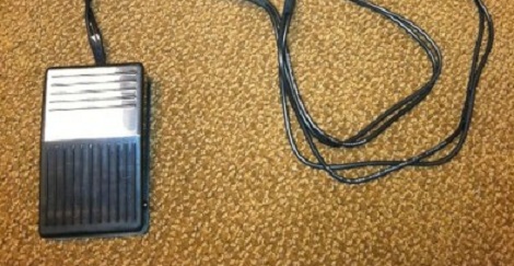
After plugging in his two DJ Hero controllers to a breakout board, [Ryan] discovered the turntables communicate on an I2C bus. A Teensy was thrown into the mix, and work began on decoding the turntable output. [Ryan] figured out that by pulling 23 bytes from the turn table, he was left with the necessary data. Byte 20 is the state of the green, red, and blue buttons, byte 21 is the distance traveled, and byte 23 indicates clockwise or counter-clockwise. After [Ryan] figured out how to pull data off his DJ Hero controllers, the only thing left to do was build a giant Etch A Sketch on a 55 inch TV.

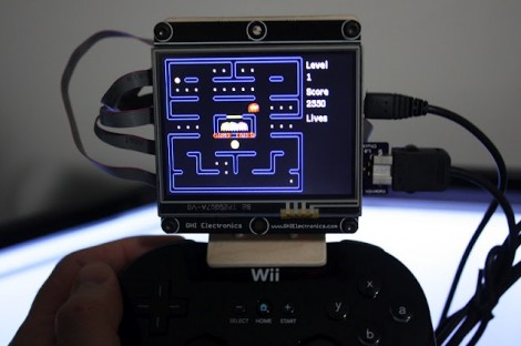
By the time the Etch A Sketch was completed, [Ryan] figured out that he had a gigantic rotary encoder – perfect for some classic MAME action. He started up MAME and loaded up Cameltry and Off The Wall. The DJ Hero controllers seem to work just fine, even if the hunched-over [Ryan] can’t beat the levels.

Building Optical Flex Sensors

[Joel] dug up this hack that he pulled off over ten years ago. It’s inspired by the Nintendo PowerGlove, and uses flex sensors to react to movements of your fingers. The interesting thing is, he built these optical flex sensors himself.

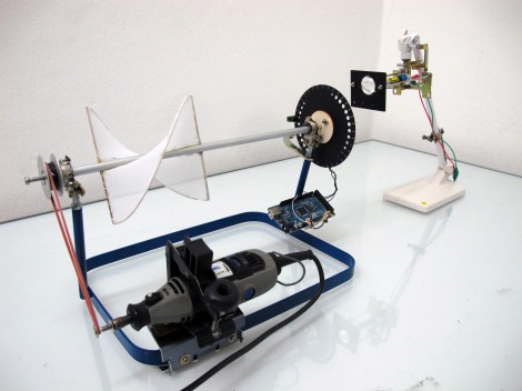
He likes to say that this is a ghetto fiber-optic setup. The inlaid diagram above gives you an idea of how the sensors work. An IR LED and infrared diode are positioned at either end of a piece of clear aquarium tubing. When the tube is flexed, the amount of light that makes it to the diode is diminished, a change that can be measured by a microcontroller. [Joel] found that he could increase the resolution of the sensor by adding something to the center of the tube, blocking the light when not straight. In this case he used pieces of scrap wire. The outside of the sensor was also wrapped in shrink tubing to keep ambient light from interfering with measurements.

He uses a trimpot to tune the sensors but we wonder how hard it would be to add a calibration algorithm to the firmware?

A Wooden Computer Case, Monitor Stand, And Keyboard

Wood and electronics don’t generally mix nowadays, but if you yearn back to a time when radios and the like had a nice wooden finish, this wooden computer case may be for you. Combine that with a Wooden keyboard enclosure, and maybe even a LCD monitor stand and you’ll have a setup that should fit in with any wood-themed decor!

The wooden computer case is actually more of a cover in that it uses most of the stock case to house all of the components.  It would definitely be a pain, and possibly a fire-hazard, to make a back mounting plate for all the components out of wood. To go along with this, the LCD monitor stand was engineered for a 21″ monitor when the owner of it wasn’t satisfied with the stability of the stock stand.  In the end, he ended up building something quite sturdy and nice looking to replace it.

The highlight for many for the keyboard would be that it was made, in part at least, out of a desire for a Commodore-64 keyboard.  It appears to function well andlooks great, so be sure to check out the other pictures after the break! Continue reading “A Wooden Computer Case, Monitor Stand, And Keyboard”

C64 Joystick Adapter

[Marcus Gritsch] wanted to do his retro gaming using retro hardware… or at least using some retro hardware. Although he was playing his Commodore 64 games in an emulator, he figured that using an original controller would boost the nostalgia quite a bit. This is a vintage Competition Pro joystick that has buttons and a joystick of a similar quality to arcade hardware and a DE-9 connector. He managed to connect new to old by building his own USB to C64 joystick adapter.

His project started out by breadboarding a circuit based on a PIC 24FJ64GB002 microcontroller. This does all of the work, having native USB support, and no problem reading and translating the signals from the old hardware which are simply conductors for each internal switch that pull to ground when actuated. Once working, he soldered everything to some protoboard; a connector at each end, the chip itself, a voltage regulator, and some passive components. It’s a, robust build that should give him years of emulated fun.

Hardware-based Keyboard Remapping

[Nav] wanted to change his keyboard mapping for one particular keyboard, rather than on each operating system. He used an AT90USBKey as a replacement PCB by soldering to all of the contacts on the key matrix. This allows him to remap the keys by following onscreen prompts.

The board enumerates as an HID device, and has a special mode which is accesses by plugging the keyboard in while holding down any key. If a text editor window is active you’ll see prompts from the microcontroller to press a series of keys. This is a routine used to learn how the key matrix is organized, and it’s your opportunity to change how each key is mapped. Since the mapping is saved to EEPROM, you can use any computer to map the keys, then plug the device into a systems that don’t offer software remapping. It could also be useful as a gaming keyboard, assuming there aren’t latency issues

As with the AVR-based arcade controller, this project uses the LUFA package to handle the USB stack.

Open Source Makes This USB Arcade Controller Build A Breeze

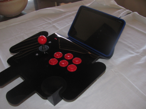
[Jamie] built his own USB connected arcade controller. We’ve been seeing a lot of these lately, and they usually involve soldering buttons to a keyboard PCB. But [Jamie] decided to go a different route and use his own microcontroller. This method always gets a bit hairy when it comes to deciding how to connect it to a computer. Dealing with the USB stack used to be quite tricky, but the LUFA project is slowly taking the pain out of the process.

The Lightweight USB Framework for AVRs is an open source project that handles the hard work associated with USB capable AVR microcontrollers. [Jamie] knew that they already had a sample implementation of a hardware joystick. He’s not using one of the supported boards and so wasn’t able to just compile and go. But porting the code to work with his minimus board was simple enough. With the code in place, the physical build was quite simple. The buttons and joystick were mounted on the surface of an overturned drawer. Each is connected to one pin of the controller board and to ground. LUFA makes sure that the device enumerates as a joystick, and [Jamie] was gaming in no time.

Star Wars Imperial March Played By Dual Floppy Drives

Although many have made some sort of music with improvised electronics, few sound as cool as this Imperial March from Star Wars played by two floppy drives. According to [Pawel], “It’s nothing new” and quite simple. This may be true as we’ve featured an Imperial March-playing floppy drive here before, but it was only one drive. Although it may not be the London Symphony Orchestra, the two drives together sound quite good!

According to him, the FDD has a fairly simple interface. To move the head, one simply needs to pull the DRVSB pin low and then activate the STEP pin on a falling edge.  This will make the head move one direction dependent on the DIR pin state. In this case, an ATMega microcontroller is moving everything. An explanation of the pins used in this hack can be found here.

Although it may look like an intimidating hack on the surface, something like this might be a neat project to try with some old hardware and an Arduino or other controller! [Pawel] did have the idea to hook up a 5 1/4″ and 8″ drive to make a full FDD orchestra, so we can’t wait to see what he comes up with! Continue reading “Star Wars Imperial March Played By Dual Floppy Drives”