A Technique To Avoid Warping On Large 3D Prints

[Jamie Mantzel] figured out his own way of 3D printing large objects without fear of warping. First a bit of background information. When using a 3D extrusion printer like the RepRap or Makerbot, prints that span a large area tend to warp. That’s because these printers lay down one thin layer of plastic at a time. If the first layer cools too much, it will shrink a bit before the next layer is laid down. As that second layer cools it pulls the part toward the center, eventually bowing the part which causes it to hit the extruder head.

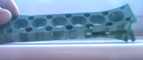
After having several prints encounter this issue [Jamie] decided to alter his design so that it wouldn’t cause these stresses. The first thing that he did was to add alternating voids to a layer between the raft and the actual part. You can see these as notches on the bottom the piece pictured above. This takes care of the initial stresses from the first layer. Next, he adds holes wherever he can in the main body of the part. This is especially important on the edges of the piece where the warping forces will be the greatest.

He also moved the starting position of the bed closer to the extruder head. His hope is that this will help the raft bond better, and resist pulling away from the bed during printing.

See his video explanation of his adventure after the break.

Continue reading “A Technique To Avoid Warping On Large 3D Prints”

DIY LED Photography Lights

led-light-box

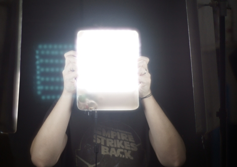
[Markus] had been drooling over some LED panels to use as a soft light source for photography, but being a hobbyist, he didn’t want to spend a ton of money to buy them. He figured that he had enough electronics know-how to build his own panels, while saving a boatload of cash in the process.

He hoped to keep the total cost under £100, so along with new items like LED light strips, he would have to use some stuff he had sitting around, like the metal cooking containers that make up the body of the lights. While originally planned for use in a different project, it turns out that the cooking containers were ideal for his lighting setup, since they are both durable and great heatsink material.

The remainder of the build is pretty straightforward. [Markus] used a pre-made LED dimmer to control the panel’s brightness, along with some tinted plexiglas to diffuse the light while bringing the color temperature into a more usable range.

While he missed his £100 mark, the lights look great – we just might have to build a few of them ourselves.

Snake-bot Gives Us The Mechanical Heevy-jeevies

Basilisk? Nope, just your run-of-the-mill giant serpentine robot build. This build aims to recreate Titanoboa, a prehistoric snake which measured more than fifty feet long and weighted over a ton. They’re well on their way to completing the goal, as what you see above is fully operational, lacking only cosmetic niceties which would only serve to make the beast less horrifying.

The video after the shows the snake getting round an open space, presumably at the eatArt headquarters in Vancouver. You may remember the team from one of their other builds also featured in that clip, the Mondo Spider. Eventually, the snake will have a rider just like the spider does, sitting in a saddle mounted just behind the head. There’s few details about the hardware, but we know it’s hydraulic, and that they raised $10k to make the build possible.

For some reason seeing these bots interact gives us flashbacks to childhood cartoons. Is it possible the eatArt crew has been watching too many old G.I. Joe cartoons and the like?

Continue reading “Snake-bot Gives Us The Mechanical Heevy-jeevies”

Stylophone 5 – Modernizing The Best Of The 1968 Hardware

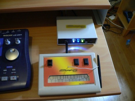
We love looking in on [Simon Inns’] projects, and this must be one of his very best. This is the fifth version of his MIDI-capable stylophone. The gist of the control system is that a conductive keyboard (made of a tinned PCB) is played by making a connection with the tip of a wired stylus — hence the name. The idea comes from the original 1968 Dubreq Stylophone hardware, but [Simon’s] not just using the idea. He has his own working original and used it to reverse engineer the circuit design.

When it first came out, the Stylophone had three flavors for Bass, Standard, and Treble audio ranges. They differed only in the choices of passive components used in the circuit. [Simon] built the variations into his design so that they are selectable on one unit. This most recent version connects via USB, allowing you to control MIDI software. But unlike his first four iterations, this also offers MIDI-In capabilities. This makes it possible to control tuning, vibrato, and to drive the Stylophone circuitry from the computer interface. Get a good look at that, and a nostalgic Portal moment, by watching the clip after the break.

If you’re looking for an easier build, you might try this analog standalone version of the Stylophone.

Continue reading “Stylophone 5 – Modernizing The Best Of The 1968 Hardware”

Audio Output Selection Courtesy Of The Internet

[Peter] was tired of crawling behind his desktop computer to switch between headphones and speakers. We feel his pain, as the headphone port on our computer speakers has its own demonic hum rendering the jack useless to us. His solution was to build this output selector board, then control it via the network.

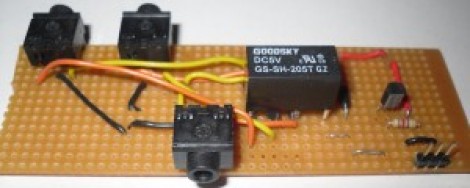
A relay is responsible for routing the single input to one of two outputs. One output is wired to the normally closed pin on the relay, the other to the normally open pin. The important thing here is to make sure you have a separate audio ground so as not to pick up noise from the rest of the hardware.

What you see above is only the switching circuitry. This is where [Peter] went a little overboard, using an Arduino along with an Ethernet shield to drive the relay via a transistor. For this particular application there must be an easier way. But if you’re working on home automation from your smart phone, this might be just the thing to make your audio setup browser-controlled.

[via Build Lounge]

ColorHug: A Reasonably-priced, Completely Open Color Calibration Tool

colorhug-opensource-color-calibrator

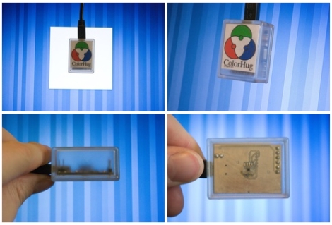
[Richard] wanted to create a color profile for his computer monitor, but he wasn’t thrilled with the existing color calibration offerings he found for sale. Color calibration tools can be somewhat costly, but even more troubling to [Richard] was the fact that they are all closed source. Closed hardware and closed software can be a drag, especially when manufacturers drop support for a product, so he set off to design his own open-source monitor calibration tool.

Once his ColorHug sensor is placed against a monitor, it begins sampling colors from the screen, creating an ICC color profile from the data it gathers. The sensor is a Linux-only tool at the moment, but he has created a live CD from which a color profile can be created, then subsequently used in Windows or OSX.

While ColorHug doesn’t sport all the features of its commercial competitors, its color sampling rate is second to none, and since the software is open, anyone is free to implement any sort of functionality they wish.

[Richard] is currently selling finished ColorHug modules to anyone interested in giving them a test drive, but you can always build your own from the plans found at ColorHug’s Github repository.

[via Adafruit blog]

Solder Reflow Toaster Oven

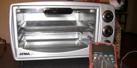
[Sebastian] needed a small solder oven so he bought himself a small toaster oven (Spanish, Google Translate). It’s not the kind of thing we’d make our breakfast in now, but for soldering it’s a very nice oven.

After a little bit of research on Google, [Sebastian] discovered that the best technique when dealing with reflow ovens and solder paste is following a specific temperature curve. Ideally, Tin/Lead solder needs to preheat from room temperature to 150 degrees C, then level off so the flux can activate. After that, a quick jaunt above 183 degrees C makes the solder flow. To get his toaster working optimally, [Sebastian] stuck a thermistor in the toaster and measured the temperature profiles of different ‘modes.’

The correct temperature curve was calculated using different heater elements and [Sebastian] was off to the races. He did have a few problems on his first few boards – solder bridging, mostly – but that’s not the fault of the oven. An LCD display (translate) was added recently so accurate real-time temperature monitoring is available.