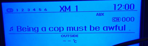
The subreddit for Shower Thoughts offers wisdom ranging from the profound to the mundane. For example: “Every time you cut a corner you make two more.” Apparently, [Harin] has a bit of an addiction to the subreddit. He’s been sniffing the CAN bus on his 2012 Hyundai Genesis and decided to display the top Shower Thought on his radio screen.
To manage the feat he used both a Raspberry Pi and an Arduino. Both devices had a MCP2515 to interface with two different CAN busses (one for the LCD display and the other for control messages which carries a lot of traffic.
The code is available on GitHub. There’s still work to do to make the message scroll, for example. [Harin] has other posts about sniffing the bus, like this one.
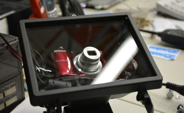
Looking for a high quality security camera? Despite digital cameras continually getting better, and less expensive, security cameras haven’t seemed to follow the same path. So? Better make your own.
[donothingloop] was looking for an outdoor, network capable camera of high resolution. He Some people might have thought about using the Raspberry Pi camera module, but let’s be honest — it’s not great. Instead, he found a pair of used Nikon Coolpix L31 cameras, and he only paid $15 for the both of them.
Now the Nikon Coolpix L31 isn’t exactly the sports edition, so to make this an outdoor security camera, it’s going to need an enclosure. An outdoor halogen work lamp enclosure fit the bill perfectly. It’s rugged, already has the glass built into it, and at $12 the cost of this project wasn’t going anywhere!
One of the nice things about the Raspberry Pi is that it runs Linux and you can do a lot of development right on the board. The converse of that is you can do a lot of development on a Linux desktop and then move things over to the Pi once you get the biggest bugs out. However, sometimes you really need to run code on the actual platform.
There is, however, an in-between solution that has the added benefit of upping your skills: emulate a Pi on your desktop. If you use Linux or Windows on your desktop, you can use QEMU to execute Raspberry Pi software virtually. This might be useful if you don’t have a Pi (or, at least, don’t have it with you). Or you just want to leverage your large computer to simplify development. Of course we would be delighted to see you build the Pi equivalent of the Tamagotchi Singularity but that’s a bit beyond the scope of this article.
Since I use Linux, I’m going to focus on that. If you insist on using Windows, you can find a ready-to-go project on Sourceforge. For the most part, you should find the process similar. The method I’ll talk about works on Kubuntu, but should also work on most other Debian-based systems, including Ubuntu.
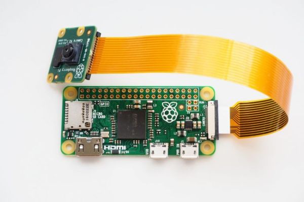
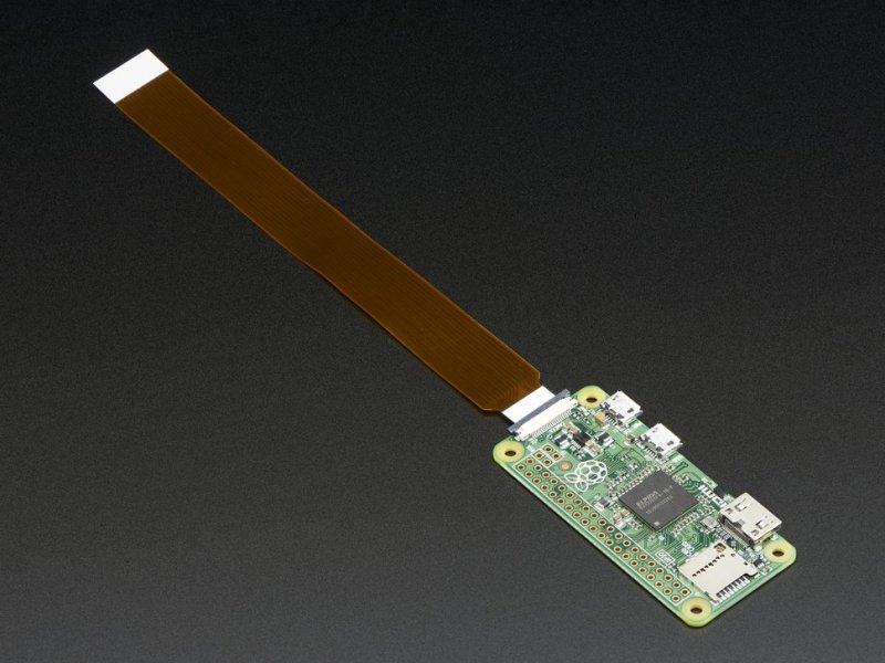
The latest version (1.3) of everyone’s favorite $5 computer now sports a frequently requested feature: a camera connector. The Pi Zero will now use the same economical camera modules available for the full-sized Raspberry Pi units.
The price of the Pi Zero is unchanged at $5, but there is a small catch. While the Raspberry Pi camera modules themselves will work just fine on the Pi Zero, the usual camera cable they come with will not. The Pi Zero’s camera cable connector is a little smaller than the ones on the full-grown Pi, so it needs a special cable to interface the camera modules to the slightly smaller connector found on the Pi Zero.
This should be good news. The new connector has appeared because another production run is ramping up. Logic points to greater availability of the $5 wonder board, but we’re still not holding our breath.
Pi Zero with camera module connector cable. [Image source: Adafruit]With the Pi Zero now able to use camera modules, perhaps camera-based Pi projects like these digital binoculars or time-lapse camera rigs can now get even smaller.
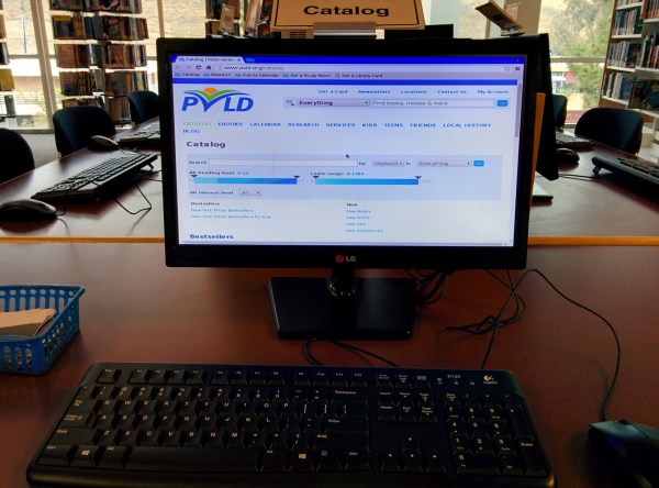
Here’s a great real-world use case for the Pi—a small job for a small computer. [viking–] works in a public library. Like many public libraries, this one has catalog-only terminals that are separate from the computers you reserve to get your fix of cat videos and Bejeweled Blitz. The catalog computers needed to be upgraded, and [viking–] replaced them all with Raspis.
They’re all running Raspbian and boot directly into Chromium with a clean profile every time. The Pis are otherwise completely locked down and accessible only through SSH. A dedicated WiFi network and whitelisted web access help keep them secure. The Pis reboot after five minutes of inactivity which erases all login credentials and bookmarks.
These terminals are scattered throughout the library. Those closest to the front desk have their Pi in a VESA mount on the back of the monitor. The others are locked up in cabinets so they don’t get pinched by the patrons. Library budgets are lean enough already. [viking–] was able to get management sign-off for the project by building a single prototype to show the simplicity of the system and the projected cost savings. Thanks to a couple of cron jobs, the Pis shut the monitors down every night, saving hundreds of dollars per year.
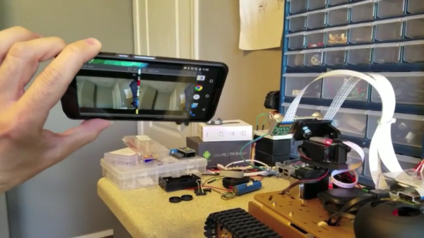
It’s great to see different kinds of hardware and software tossed into a project together, allowing someone to mix things that don’t normally go together into something new. [Freddy Kilo] did just that with a project he calls his VR Robot Tank. It’s a telepresence device that uses a wireless Xbox controller to drive a tracked platform, which is itself headed by a Raspberry Pi.
The Pi has two cameras on a pan-tilt mount, and those cameras are both aimed and viewed via a Google Cardboard-like setup. A healthy dose of free software glues it together, allowing things like video streaming (with U4VL) and steering via the wireless controller (with xboxdrv). A bit of fiddling was required for some parts – viewing the stereoscopic cameras for example is done by opening and positioning two video windows just right so as to see them through the headset lenses. It doesn’t warp the image to account for the lens distortion in the headset, and the wireless range might be limited, but the end result seems to work well enough.
The tank is driven with the wireless controller while a mobile phone mounted in a headset lets the user see through the cameras; motion sensing in the phone moves those cameras whenever you move your head to look around. Remote Control hobbyists will recognize the project as doing essentially the same job as FPV setups for model aircraft (for example, Drone Racing or even Snow Sleds) but this project uses a completely different hardware and software toolchain. It demonstrates the benefits of having access to open tools to use as virtual “duct tape”, letting people stick different things together to test a concept. It proves almost anything can be made to work if you have a willingness to fiddle!
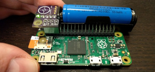
Knocking a microcontroller into sleep mode and waking it up on demand or in intervals is common practice in many low power applications, enabling devices to stay in operation for years on a single coin cell battery. Since there are tons of applications where you might want to do similar things with a Raspberry Pi, [Patrick Van Oosterwijck] created the LiFePO4wered/Pi. The module that snaps on to eight GPIO pins of a Pi, extending it by a long life LiFePO4 battery, a charging regulator, and a proper power management. Obviously, it also makes a great UPS.
[Patrick] realized this project by expanding his already available and equally useful LiFePO4wered/USB charging regulator module by a low power MSP430G2131 microcontroller and a load switch. A daemon on the Raspberry Pi speaks to the module over I2C, allowing you to schedule a wake-up timer, let your Pi autoboot after a power outage or just read out the current battery voltage through a command line tool. Once the Pi is safely shut down, the microcontroller will also go to sleep, resulting in a standby current of 8 uA for the whole system. Together with the 500 mAh LiFePo4 cell, that’s theoretically low enough to send your Pi-ncess into a seven-year-long sleep.
LiFePO4wered/Pi is not only good for sleeping, though. [Patrick’s] runtime tests show, that the 500 mAh cell will power a Raspberry Pi Zero and a WiFi dongle for about two hours. Because the Raspberry Pi and many USB peripherals won’t complain when only 3.2 V are present on the VBUS, [Patrick] was able to squeeze out even more runtime by dismissing the boost converter from the design and driving the Pi directly from the battery voltage. If that worries you, you can either read a detailed explanation on why that works so well or just have a look at the more compliant 5 V version.
Eventually, [Patrick] used his module to create a Raspberry Pi time-lapse camera. A little script lets the Pi take a picture on boot up, set a wake-up timer and go back to sleep again. Safely enclosed in a waterproof electric box and deployed into the wild, the camera took 120 pictures on a single charge.
We’re sure the module will find it’s way into many cool projects and we’re counting the hours until we can get one in [Patrick’s] tindie store. Until then, enjoy the time-lapse video: