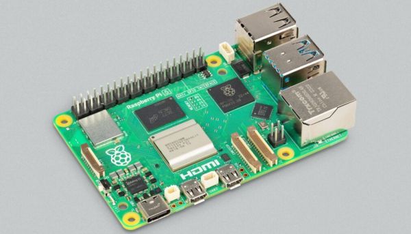
Mechanical Keyboard As Travel Saxophone

Those who play larger musical instruments, things like drums, piano, harp, tuba, upright bass, or Zeusaphone, know well the challenges of simply transporting their chosen instrument to band practice, a symphony hall, or local watering hole. Even those playing more manageably-sized instruments may have similar troubles at some point especially when traveling where luggage space is at a premium like on an airplane. That’s why [jcard0na] built this electronic saxophone, designed to be as small as possible.

Known as the “haxophone”, the musical instrument eschews the vibrating column of air typical of woodwind instruments in favor of an electronic substitute. Based around the Raspberry Pi, the device consists of a custom HAT with a number of mechanical keyboard switches arrayed in a way close enough to the layout of a standard saxophone that saxophonists will be able to intuitively and easily play. Two pieces of software run on the Pi to replicate the musical instrument, one that detects the player’s breaths and key presses, and another that synthesizes this information into sound.

While [jcard0na] notes that this will never replicate the depth and feel of a real instrument, it does accomplish its design goal of being much more easily transportable than all but the most soprano of true saxophones. As a musical project it’s an excellent example of good design as well, much like this set of electronic drums with a similar design goal of portability.

New Raspberry Pi Camera With Global Shutter

Raspberry Pi has just introduced a new camera module in the high-quality camera format. For the same $50 price you would shell out for the HQ camera, you get roughly eight times fewer pixels. But this is a global shutter camera, and if you need a global shutter, there’s just no substitute. That’s a big deal for the Raspberry Pi ecosystem.

Global vs Rolling

Most cameras out there today use CMOS sensors in rolling shutter mode. That means that the sensor starts in the upper left corner and rasters along, reading out exposure values from each row before moving down to the next row, and then starting up at the top again. The benefit is simpler CMOS design, but the downside is that none of the pixels are exposed or read at the same instant.

Continue reading “New Raspberry Pi Camera With Global Shutter”

Pi Picos Give Casio FX9000P Its Memory Back

Is the Casio FX9000P a calculator or a computer? It’s hard to tell since Casio did make calculators that would run BASIC. [Menadue] didn’t know either, but since it had a CRT, a Z80, and memory modules, we think computer is a better moniker.

He found one of these, but as you might expect, it needed a bit of work. There were two bad video RAM chips on the device, and [Menadue] used two Raspberry Pi Picos running a program to make them think they are RAM chips. The number of wires connecting the microcontollers might raise some eyebrows, but it does appear to get the job done.

He also used more Picos to emulate memory on cartridges. Then he used a test clip and a — you guessed it — another Pico to monitor the Z80 bus signals. It is amazing that the Pico can replace what would have been state-of-the-art memory chips and a very expensive logic analyzer.

The second video mostly shows the computer in operation. The use of Picos to stand in for so much is clever. It reminded us of the minimal Z80 computer that used an Arduino for support chips. The computer itself, though, reminded us more of a cheap version of the HP9845.

Continue reading “Pi Picos Give Casio FX9000P Its Memory Back”

Showing a RAM chip being removed from a Pi 4 board, hot air gun in the shot. Area around the chip is covered with kapton tape.

Upgrade RAM On Your Pi 4, The Fun Way

The Raspberry Pi shortage has been a meme in hacker circles for what feels like an eternity now, and the Pi 4 seems to be most affected – though, maybe it’s just its popularity. Nevertheless, if you’re looking for a Pi 4, you would need to look far and wide – and things are way worse if you need the 8 GB version specifically. Or so we thought – [MadEDoctor] shows us that refreshing online store pages isn’t the only way, having successfully upgraded the RAM chip on the Pi 4 from 1 GB to 8 GB with help of a hot air gun.

These chips are BGA, and those might feel intimidating if you’re just starting out with hot air – however, we recommend you watch this video, as [MadEDoctor]’s approach is of the kind that brings BGA replacement to hobbyist level. First off, you get a compatible RAM chip somewhere like Aliexpress – lucky for us, those come equipped with a set of balls from the factory. The default balls are made of lead-free solder, and [MadEDoctor] reballed the RAM chip with leaded solder balls to lower the melting point, but it’s by no means a requirement that you do the same.

In fact, you only need a hot air gun, flux, a soldering iron and some solder wick to perform the replacement – no reballing equipment. Put some kapton or metal tape on the board for heat shielding, get the old chip off with hot air, use an iron with wick to clean the pads, add some flux, align the chip, then use hot air to solder a new chip onto the board. Replacing this chip can get your Pi 4 to the highly-sought-after 8 GB target – as an aside, we’re surprised that there was no configuration needed, as the Pi 4 booted right up and successfully recognized the extra RAM added.

We’d personally recommend preheating for such an upgrade – that said, this sure went without a hitch, and such a RAM swap method doesn’t require any stencils, solder paste or solder ball applications. Drop by the video description for compatible RAM chip part numbers, make sure you have your tacky flux and solder wick in order, and let [MadEDoctor] walk you through upgrading your Pi 4 the hacker way. Is this hack to your liking? Take it up a notch with this laptop soldered-in RAM upgrade journey, or that one RAM upgrade for an old GPU to comply to Apple’s whims.

Screenshot of the code decompiled after these patches are applied, showing that all the register writes are nicely decompiled and appropriate register names are shown in the code

Making Ghidra Play Nice With RP2040

Developing firmware for RP2040 is undeniably fun, what’s with all these PIOs. However, sometimes you will want to switch it around and reverse-engineer some RP2040 firmware instead. If you’ve ever tried using Ghidra for that, your experience might have been seriously lackluster due to the decompiled output not making sense when it comes to addresses – thankfully, [Wejn] has now released patches for Ghidra’s companion, SVD-Loader, that turn it all around, and there’s a blog post to go with these.

SVD-Loader, while an indispensable tool for ARM work, didn’t work at all with the RP2040 due to a bug – fixed foremost. Then, [Wejn] turned to a pecularity of the RP2040 – Atomic Register Access, that changes addressing in a way where the usual decompile flow will result in nonsense addresses. Having brought a ton of memory map data into the equation, [Wejn] rewrote the decoding and got it to a point where peripheral accesses now map to nicely readable register writes in decompiled code – an entirely different picture!

You can already apply the patches yourself if you desire. As usual, there’s still things left in TODO for proper quality of life during your Ghidra dive, but the decompiled code makes way more sense now than it did before. Now, if you ever encounter a RP2040-powered water cooler or an air quality meter, you are ready to take a stab at its flash contents. Not yet familiar with the Ghidra life? Well, our own HackadayU has just the learning course for you!

Testing The Raspberry Pi Debug Probe

We mentioned the Raspberry Pi Debug Probe when it was launched, a little RP2040-based board that provides both a USB-to-UART and an ARM SWD debug interface. [Jeff Geerling] was lucky enough to snag one, and he’s put it through its paces in a handy blog post.

The first question he poses is: why buy the Pi offering when cheaper boards can be found on AliExpress and the like? It’s easily answered by pointing to the ease of setting up, good documentation and support, as well as the device’s reasonable price compared to other commercial probes. It also answered a personal question here as he hooked it up to a Pico, why it has three jumpers and not the more usual multi-way header we’ve seen on other ARM platforms. We should have looked at a Pico more closely of course, because it matched neatly to the Pi product. On the Pico they’re at the edge, while on the Pico W they’re in the center.

No doubt if the latest addition to the Pi stable has any further revelations we’ll bring them to you. But it’s worth a quick look at this piece to see a real experience with their latest. Meanwhile, take a quick look at our launch coverage.

New Product: The Raspberry Pi Debug Probe

It’s fair to say that among the new product launches we see all the time, anything new from the folks at Raspberry Pi claims our attention. It’s not that their signature Linux single-board computers (SBCs) are necessarily the best or the fastest hardware on paper, but that they’re the ones with meaningful decade-plus support. Add to that their RP2040 microcontroller and its associated Pico boards, and they’re the one to watch.

Today we’ve got news of a new Pi, not a general purpose computer, but useful nevertheless. The Raspberry Pi Debug Probe is a small RP2040-based board that provides a SWD interface for debugging any ARM microcontroller as well as a more generic USB to UART interface.

The article sums up nicely what this board does — it’s for bare metal ARM coders, and it uses ARM’s built-in debugging infrastructure. It’s something that away from Hackaday we’ve seen friends using the 2040 for as one of the few readily available chips in the shortage, and it’s thus extremely convenient to have readily available as a product.

So if you’re a high level programmer it’s not essential, but if you’re really getting down to the nuts-and-bolts of an ARM microcontroller then you’ll want one of these. Of course, it’s by no means the first SWD interface we’ve seen, here’s one using an ESP32.