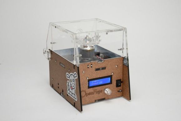
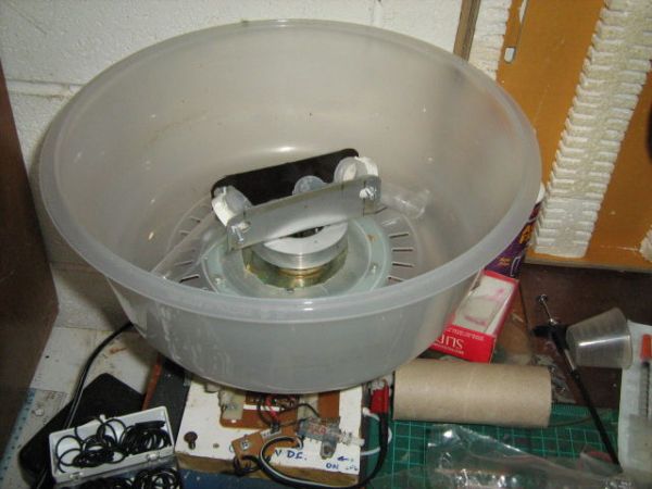
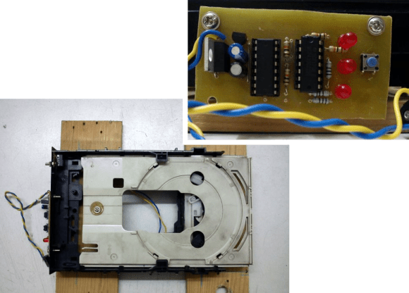
Biohackers, fire up your laser cutters. [CopabX] has developed OpenFuge: a (relatively) low-cost, open-source centrifuge from powerful hobby electronic components. If you thought the VCR centrifuge wasn’t impressive, trolls be damned— OpenFuge can crank out 9000 RPM and claims it’s capable of an impressive 6000 G’s. [CopabX] also worked in adjustable speed and power, setting time durations, and an LCD to display live RPM and countdown stats.
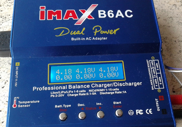
And it’s portable. Four 18650 lithium cells plug into the back, making this centrifuge a truly unique little build. The muscle comes from a DC outrunner brushless motor similar to the ones that can blast you around on a skateboard but with one key difference; an emphasis on RPMs over torque. We’re not sure exactly which motor is pictured, but one suggestion on the bill of materials boasts a 6000 KV rating, and despite inevitable losses, that’s blazing fast at nearly 15V.
You’ll want to see the demonstration video after the break, but also make time to swing by Thingiverse for schematics and recommended parts.
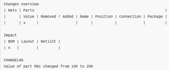 We love Git. We know everyone has their favorite version tracking tools. But even those that don’t care for Git should see the value of


