Chrono-tomic Shield Helps Your Arduino Keep Perfect Time

chronotomic-arduino-shield

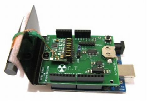
[Josh] and his lab partner [Eric] needed a final project for their Embedded Systems Design class, and thought that designing an Arduino shield would be a cool idea. They noticed that there are plenty of ways to get an Arduino to keep time, though none that they knew of utilized WWVB (Atomic Time) signals directly.

The Chrono-tomic Arduino shield uses a C-MAX radio to demodulate the WWVB signal, demodulating it and passing it along to a PIC16F1824 microcontroller. The PIC decodes the data frame and verifies it is valid, sending the time to an MCP79410N real-time clock module.

We can hear the “Yo dawg I herd you like microcontrollers so I put a microcontroller on your microcontroller shield” jokes already, but the pair says that they offloaded the time processing to the PIC in order to let the Arduino focus on whatever tasks it has been delegated. The Arduino code merely needs to request the time from the RTC whenever it is required, rather than deal with the decoding itself.

Is it overkill? Perhaps – though we think it heavily depends on your application and configuration. We can certainly conjure up situations where it would be useful.

arduino-seismic-sensor

Detecting Seismic Waves With A Piezo Element

While we normally see piezo elements being used to output audio, [Veedo] thought that they could be used in a more useful manner. He bought way too many piezo film tabs and decided to use them to build a makeshift seismic sensor.

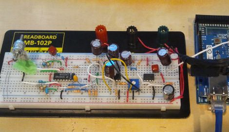
The piezo tabs came with weights attached at one end, though while testing them, he found that they more or less only detected vibrations with frequencies in the KHz range. Since earthquakes tend to produce vibrations in the 30-80 Hz range, he had to tweak his setup to detect the proper frequencies. To do this, he attached a weight made of a screw and washers, checking the output signals on his oscilloscope until the dominant sensed frequencies were in the range of 40 Hz.

The sensor was attached to a breadboard, then wired through a charge amp to create a small AC signal, which floats on 2.5Vdc. The bottom half of the wave is chopped off with a diode, after which it is fed into an Arduino Mega. The seismic data is then pushed up to his Pachube account for storage, though he can view the feeds locally via the a web server programmed into the Arduino.

We’re not sure how much advanced notice this sort of setup would give you in the event of an earthquake, but it seems like a fun project to build either way.

Christmas Tree Water Sensor Gets An Upgrade And A Fancy New Box

xmas-tree-water-sensor

[Eric Ayars] has a nice cast iron Christmas tree stand at home, but the only drawback is that the stand makes it hard to see just how much water is available to the tree. Last year we covered a small gadget he created to help keep tabs on the water level, but as several of you predicted, the system eventually failed.

His previous solution used copper plated proto board to sense how much water was in the stand, but the leads corroded in about a week’s time. With Christmas just around the corner, he decided to give things another try.

His revamped water level sensor relies on measuring capacitance changes in a copper strip board when under water rather than detecting a complete circuit like the previous model. To protect his sensor this time around he coated the board with polyurethane, which should provide a decent corrosion barrier.

Using the Arduino CapSense library, the sensor can detect the presence of water, signaling an alarm if the base needs refilling. One of our readers suggested that he use the tree itself as a low water indicator, which is just what [Eric] did this year. If the water is somewhat low, the Arduino-controlled relay powering the tree is switched off and then on again, every 5 seconds. If the base is nearly dry, the tree asks for water by blinking the word “Water” repeatedly in Morse code.

We think that this year’s solution is pretty clever, and we’re glad to see that [Eric] didn’t give up after last year’s setback!

Web-enabled Coffee Maker Over-complicates Your Break Time

Some think that grinding the beans and filling the coffee maker is part of the coffee-drinking ritual, but [Jamie] isn’t one of them. Instead, he’s been working to make this coffeemaker a web-enabled device. He built it as part of a class project, and has implemented most of what you need to make a cup of Joe automatically.

You can see a small pump attached to the back of the coffee maker. It sucks water from a pitcher (slightly visible to the left of the coffee maker) to fill the reservoir. He experimented with a couple of different water level sensing solutions. His most recent is a PCB with several traces of different length. As those traces are covered by water, a voltage can be read via ADC to establish water level.

He’s using an Arduino and Ethernet shield to add connectivity for the device. The problem is that there aren’t enough ADC pins left on the Arduino to read the water level sensor. Because of this, he added a self-build shield that uses a PIC to do the ADC measurements and push digital data across to the Arduino. A bit complicated, and it doesn’t load the grounds automatically (yet?). But that’s not to say we don’t appreciate complicated coffee hacks.

Ethernet Controlled Garage Door

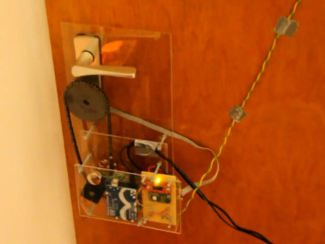
[Thomas]’ garage door opener is a big old industrial unit, so he doesn’t have the convenience of a remote-controlled garage door opener.  Obviously, this would get annoying after a while, so [Thomas] decided to build an Ethernet enabled relay board so he can open his door with his iPhone.

The build is based around an ATMega328 and a neat little Ethernet controller from Microchip. There are two relays on the board that connect to the Up and Down buttons on the door opener. The board receives UDP packets with instructions like, ‘RELAY 2 ON’ and the door responds accordingly.

Building just one of his boards cost [Thomas] the meager sum of $43. Considering the new Arduino Ethernet board costs around $60, we’re thinking he did a good job here. From the video after the break, we’re seeing that [Thomas] has to hold the button on his iPhone down for the door to go up. We see a few more pins on his AVR, so perhaps v.2 of his board could contain a few headers to attach sensors. Still, it’s a very nice build.

Continue reading “Ethernet Controlled Garage Door”

An Iambic Keyer In 5 Minutes

When most people think about a telegraph key, a piece of 1890s tech with a lever that moves up and down comes to mind. These ‘straight keys’ were terrible for telegraphers and led to repetitive stress injuries like carpel tunnel syndrome..Iambic keys came along and move the contacts to a horizontal position. If you ever see a HAM playing with his CW rig, chances are they’re using an iambic key. It’s great, then, that you can build your own iambic key in five minutes using parts you have lying around.

The build [Dimitris] put up is dead simple – just two metal contacts with a pair of 470K pullup resistors. All this connects to three pins on an Arduino. All the micocontroller needs to do is measure the rise time a touch sensor pin when a voltage is applied. If there’s a finger on the pin, the capacitance increases and the rise time is longer. After that, just assign one sensor as ‘dit’ and the other as ‘dah’ and you’ve got an iambic key.

[Dimitris] put all the code for his project up on his blog. His iambic key seems like the perfect project after a tiny Morse trainer. Check out the video of the key in action after the break

Continue reading “An Iambic Keyer In 5 Minutes”

Trying To Measure The Speed Of Light With An Arduino

We know that measuring the speed of light with an Arduino is possible. It’s just that the implementation is hard.

Last month we saw [Udo]’s blinkenlight shield that can be used as a line scan camera. It’s a neat piece of kit, but [Udo] really wants to submit something for the Buildlounge laser cutter giveaway, so he figured measuring the speed of light would be an easy project. If a kid and a chocolate bar can do it, surely it can’t be too hard.

[Udo] hit upon the idea of pulsing a laser pointer and measuring the time of the reflection. Because his blinkenlight shield can be used as a light sensor, all that’s needed is a mirror and a pretty long line of sight. There’s a few problems with the setup though: with the Arduino running at 16 MHz, a photon will travel 19 meters in one clock cycle.

Even with some very clever coding, we’re not really sure detecting an emitted photon is possible at such (relatively) slow clock speeds. We’re thinking [Udo] could source a few hundred meters of optic fiber so the entire experiment could fit on a desk, but feel free to drop a note in the comments if you’ve got a better idea. [Udo]’s demo of his blinkenlight/laser mashup is after the break.

Continue reading “Trying To Measure The Speed Of Light With An Arduino”